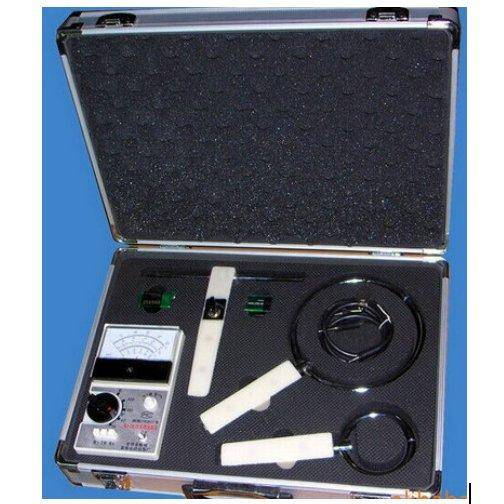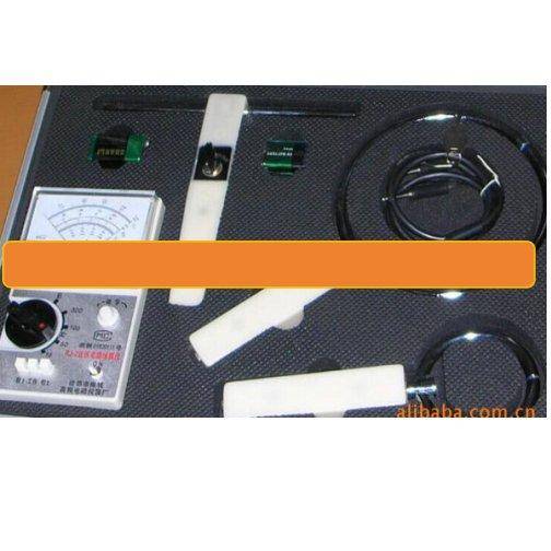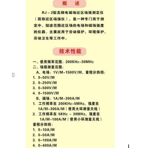


The rj-2 hf peri-area electromagnetic field power measurer is a specially designed measure of the electrical and magnetic field strength of the near-area field in the medium- and short-wave range, which is used mainly in labour protection, environmental monitoring, hygiene prevention, etc。
Technical performance
I. Frequency range: 200 khz-30 mhz
Ii. Range of field strength measurements:
A. Electricity field: 1 v/m-1500 v/m, in four steps:
1, 0-50 v/m
2, 0-250 v/m
3, 0-500 v/m
4, 0-1500 v/m
B. Magnetic field: 1a/m-300a/m
1 working frequency at 200 khz-5mhz, strength at 1a/m-300a/m, using a large ring antenna
2. Working frequency 5 mhz-30 mhz, strength 1a/m-100a/m, small ring antenna
The scale is in four
1, 0-10a/m
2, 0-50a/m
3, 0-100a/m
4, 0-300a/m
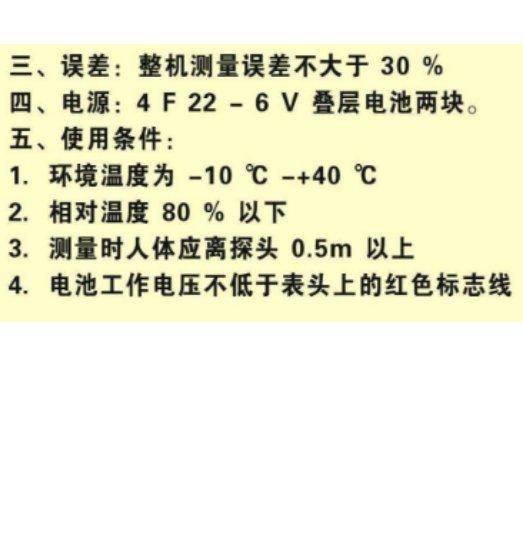
Iii. Error: 30% error in whole machine measurements
Power source: 6f22-9v, two stacked batteries。
V. Conditions for use:
1. Temperature of the environment -10°c +40°c
2. Relative temperature below 80%
3. The human body should be above detector 0. 5m at measurement
Battery working at no less than the red mark on the surface line
Electronic description
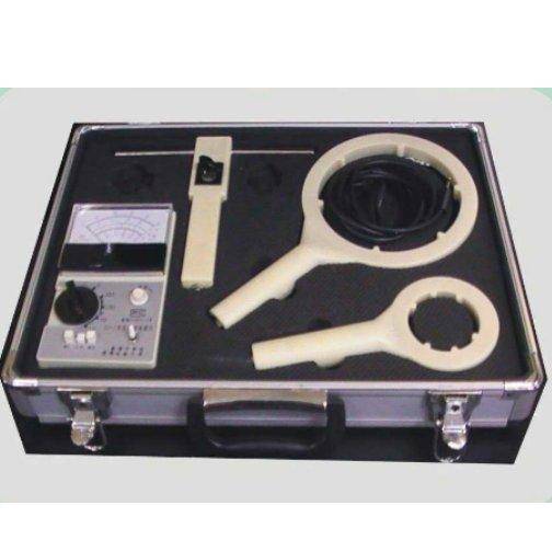
This instrument consists of electrical field probes, magnetic field probes, transmission lines (or connection plugs) and four parts of an indicator. It is illustrated below:
(electrotechnical)
The mini-octopus antenna, the decorator, the current, the filter, the ace
↓ (indicator)
B hf filter decayer resistance transformer direct current meter
Zenium
Ringed antennas, split circuits, currents, filters, filters
(magnetic probe)
After receiving the energy of the electromagnetic plant at the site, which is detected by the antenna, it is selected through the current, filtering to the direct signal through the double-crowding transmission line (or connection plug) to the indicator segment, which is shown by high frequency filters, decayers, resistance converters, and, finally, by measured magnetic field strength at the top。
Since this instrument uses field effects to resist pipe changers and the integration circuits in magnetic field probes, the strong field display is largely unrelated to the frequency of the field being detected. This instrument may be tested within the specified frequency range without a frequency error correction。
Method of application
Prepare:
Placing a task switch at “check 1”。
2. Turns on the power switch, at which point the compass shall exceed the red line, indicating that the first battery voltage is normal; then dials the switch to "check 2" to check whether the indicator of the dashboard exceeds the red line and, when both sets of battery voltages are normal, places the work switch at "work"。
3. Turn the “zero” button so that the indicator is “zero” (not plugged in to avoid external interference)。
Field measurements:
Place the quantum switches on the indicator at "e" (electricity field)。
2. Connecting the electrical field probe to the indicator with a transmission line or a connection plug。
3. Place the quantification switches on the head of the electric field at the appropriate level (if an unknown field is initially measured, it should normally be placed in the highest level)
4. Hand-held probes place the antenna into the measured part, while turning the probe to find the strongest point of the field, at which point the electrical strength of the detected part can be read directly from the surface tics. Or if the statement indicates that it is too large or too small, it should be changed in a timely manner。
Note: the hand-held probe shall be held at the bottom of the probe, the arm shall be stretched as straight as possible and the body of the surveyor shall avoid the direction of the extension of the antenna pole. No man or other metal objects shall be mounted within 1 m of the perimeter of the probe at the time of measurement。
Magnetic field measurements:
Placing an indicator on the upscale switch on the corresponding magnetic field quantities slot。
2. Connect the corresponding magnetic field probe to the indicator by a transmission line or a connection plug。
This instrument has two magnetic field probes. Use rings below magnetic field frequency of 5 mhz and smaller rings above 5 mhz。
3. Handheld probes place the antenna into the measured part, while turning the probe to find the strongest point of the field, at which point the magnetic field strength of the detected part can be read directly from the surface tics. If the statement indicates that it is too large or too small, it should be converted in a timely manner。
Note: the body of the measurer should avoid being parallel to the plane of the ring antenna. Use of connection plugs; for the use of a variety of measurements of environmental settings and measurement methods, this instrument has a two-fold connection plug. When used, insert one end of the plug into the perforation; the other end inserts the perforation of the indicator。
Notes
(i) the power supply should be shut down in a timely manner after the measurement has been completed。
(ii) the instrument shall be kept in a dry place in a timely manner when it is not in use and the battery shall be removed if it is not in use for a long period。
(iii) instruments cannot be permanently placed in a strong electromagnetic field。
(iv) the instrument is calibrated in a specially designed marking field and all adjustable elements shall not be moved at will. Re-calibration should take place at the manufacturing plant。
(v) the transmission line of this instrument shall be double-crowded and shall not be replaced by other conductors。
(vi) this instrument uses two sections of the 9v battery, which are subject to on-site inspection and always maintain a "check 1" pointer above the red mark line. As long as both sets of batteries remain above the red marker line at the time of inspection, the instrument will remain operational。
(vii) this instrument is generally used for continuous wave measurements, for reference purposes only。
(viii) when measuring wave-form asymmetric electric fields, there will be antenna asymmetries, i. E. Differences in readings when the antenna level moves at 180 degrees) attention should be paid to selecting the end of the antenna pole, generally based on the direction of the larger readings detected。
(ix) table batteries shall be placed in a positive or negative polarity and shall not be reversible to avoid damage to components such as amplifiers。