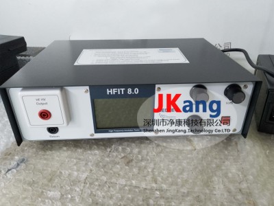



The medteq hfit 8. 0 insulation tester, the hfit 8. 0 high pressure insulation tester, is the next generation product of the hfit series, which is designed to assess compliance with iec 60601-2-2 insulation and cable leakage current tests. The standard model is designed for testing agencies that may need to process various rating values from 400 vp to 7200 vp. The model consists of four models, two of which have adjustable peak factors, which, regardless of the rating, can be designed to meet the requirements of the criteria。
Medteq hf insulation tester (hfit 8. 0) is used to test insulation associated with high frequency surgical applications, in particular the insulation of active cables and electrodes, as required by iec 60601-2-2-2 and iec 60601-2-18。
:: high frequency transmission intensity (e. G. Iec 60601-2: 2009, art. 201. 8. 8. 3. 103)
Hf leak currents (e. G. Iec 60601-2:2001, klaus 201. 8. 8. 3. 102)
Ne line insulation hf media intensity, cable leakage (iec 60601-2-2, art. 201. 15. 101. 4)
Medteq hfit 8. 0 insulation tester, hfit 8. 0 high pressure insulation tester, added the following new features to the existing hfit 7. 0:
Internal measurements and displays:
Vpeak(+vp,-vp)
Vrms
Pump factor
Irms, i'm on top
Frequency
Powder factor target
Test time
Automatic mode: user sets target peak voltage, system selection mode, adjusts voltage and peak factor
Timer function
Increased load capacity (150 pf, up to 6 kvp)
The medteq hfit 8. 0 insulation tester, the hfit 8. 0 high pressure insulation tester, is a test device designed under the iec606001-2-2: 2009 high frequency leak current and high frequency media intensity test requirements to accurately export waveform signals of cutting and multiple condensation patterns and adjust voltage and peak coefficients to test requirements for high frequency surgical devices。
Output voltage up to 7200 vp, frequency range 300-450 khz
Test load > 100 pf (equivalent to 40 to 80 centimetres of electrical capacity in salt water)
(a) provides five wave types: sine, modified sine, burst, pulse low, high high
The peak coefficient of the five waveform models can be adjusted to the need for testing
The peak coefficients are range 1. 4 to 7. 0 and meet standard requirements
(b) designing electrical and current-metric interfaces that connect oscillators to measure output voltage and leakage, without the need to purchase expensive current detectors and high-pressure detectors
Multiple protective devices to protect the safety of testers and avoid damage to equipment。
The medteq hfit 8. 0 insulation tester, hfit 8. 0 high voltage insulation tester, is designed to provide stable, reliable voltage and easily adjustable parameters as an alternative to the temporary settings historically used for hf insulation testing。
The device has four output modes: sine, correction sine, break and pulse, and is designed to cover the various wave-peak factors and peak voltage required by iec 60601-2-2-2. Two of these models (accidents and pulses) have modifiable peak factors。
For each mode, the base frequency range ranges from approximately 310 khz (full rated load) to 460 khz (unloaded), depending on the capacity of the test load. The change in base frequency is due to the use of high-power resonance circuits to achieve peaks and average loads associated with high-frequency high-pressure tests. The equipment is designed for extensive use, with a permissible load of up to 100 pf and, under many conditions, up to 150 pf。
Hfit 8. 0 has achieved new levels in this series with built-in monitoring of vp+, vp-, vrms, peak factors, irms, ipeak and frequencies. The display of peaks and square root is based on specially developed measurement systems designed to be essentially accurate in the frequency of interest, far exceeding the accuracy and reliability of existing measurement systems based on oscillators and probes。
It also provides an automated mode whereby the user simply sets the target peak voltage and presses the start button, while the rest is controlled by the system: opting for the best model and adjusting the peak voltage and wave-peak factor as required. A timer is also provided in free run and set-time mode. Automatic mode and timers make the equipment suitable for production testing。
They include system surveillance to indicate excess pressure (peaks and square root), low frequency, peak factor above target limit, overload, short circuits and internal temperature. Where appropriate, the system will also proactively reduce or stop output。
In order to set up the equipment, the user should be a qualified electrical engineer or equivalent, familiar with the high frequency insulation principle and the use of oscillators. Users should view the operating principles and significant risk components of the equipment。
