The che12-10na-h710 magnetic closeness to switch | hole sensor uses magnetic induction principles to enable internal switches to act for the purpose of breaking off points, to achieve control of external circuits and to completely overcome such characteristics as poor exposure to, and vulnerability to, mechanical collision switches。
The magnetic close to switch che12-10na-h710 is the product of the integration of the hole element with the electronic circuit, which is made of the hole element, amplifier, temperature compensation circuit and the steady voltage circuit using integrated circuit technology. It can sense all magnetic-related physical volumes and output relevant electrically controlled information, so the hole integrated circuit is both an integrated circuit and a magneticly sensitive sensor, which typically uses a dip or flatback。
The magnetic switch che12-10na-h710 is used to detect piston movements, i. E., to detect piston movements, which can be divided into nodes and nodes。
1: npn without points
2: no points pnp
3: anti-magnetic without points
The magnetic close-to-switch, which is based on the application of magnetic induction principles, has fundamentally addressed the effects from any electrical field interference. The series of switches is long-range, barrier-resistant, secure, magnetically stable, easy to install, long-lived, able to work in high temperatures, high temperatures and other adverse environments. They are widely used for location control switches, such as steel grinding, charging, shipbuilding, mines and lifting, transport, etc., or to replace the old glider contactr mechanical limit switches, as a substitute for imported national chemicals, and as an ideal component for controlling the non-contact transmission of signals.
What's a magnetic switch
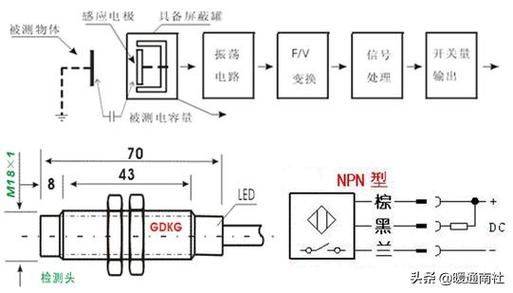
Magnetic switches are meant to be felt through magnets, which are magnets, and there are several kinds of magnets, which are commonly used on the market, such as rubber magnets, peroxides of permagnetics, sintered irons, etc. The switch is the clarinet. The clarinet is the abbreviation of a dry telecommunications larinet, a non-active electronic switch element with contact points, with advantages such as simple structure, small size and easy control, and its shell is typically a sealed glass tube containing two iron elastic disk panels and inert gases. Normally, two disks made of special materials in glass tubes are separated. When there is a magnetic substance close to the glass tube, the two magnets in the tube are magnetized and exposed to each other, and the disk is drawn together to connect the circuits attached to the nodes. When the external magnetic force disappears, the two disks are separated by their own elasticity and the lines are broken. Thus, as a circuit switch that uses magnetic field signals to control, the clarinets can be used as sensors for count, limit, etc. (mainly for door and window magnetic production in the security system) and are also widely used in various communication devices。
Magnetic switch working principles
The magnetic switch for the cylinders is to place the magnetic switch on the outside of the cylinders. The cylinders allow various types of cylinders, but they are less magnetic and highly magnetic-proof materials such as hard aluminium, stainless steel, brass, etc. When a magnetic ring of a permanent magnet (rubber magnet) is installed on a non-magnetic piston, when the magnetic ring that moves with the piston approaches the switch, the two magnets of the tongue reed switch are magnetized and attracted to each other, and their contact points are closed; when the remix switch is moved, the disk is demagnetic and the contact points are disconnected. When a point is closed or disconnected, a telecommunications signal is sent (or the telecommunications signal disappears) to control the corresponding electromagnetic valve to complete the switch. As shown in the figure below. Magnetic switches generally also have switch-activated lamps and voltage protection circuits that are wrapped in a shell with resin。
Rationale and scope of application
The hole integrated circuit is a product of the integration of the hole element with the electronic circuit, which is made of the hole element, amplifier, temperature compensation circuit and voltage circuit using integrated circuit technology. It can sense all magnetic-related physical volumes and output relevant electrically controlled information, so the hole integrated circuit is both an integrated circuit and a magneticly sensitive sensor, which typically uses a dip or flatback。
Hole's proximity switch is a new automated switch based on the hole effect principle. It is a non-tangible electronic switch with a permagnetic or conductor as the trigger medium, receiving a signal of a magnetic line through the hole effect element to control the break-up of the output. Composed of hal switch circuits, protectors, state lights, waterproof casings, etc., magnetic signals can be converted to digital voltage output. It is the preferred species to achieve position control, state control, speed measurement, counting, directional identification and automatic protection. The object of the detection shall be a magnetic object。
Product characteristics:
1. High response frequency
2. High accuracy of repeat positioning
3. Output wave pure and stable
4 with work status indication
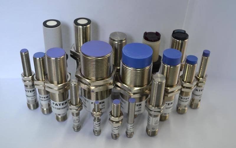
5. Stable, reliable working conditions with high levels of oil pollution, dust, vibration and temperature
6. Multiple protective features can be set up: reverse polar protection, wave voltage protection and overheat protection
7. Multiple working patterns: open, closed, self-lock, npn output, pn output
I. The rationale for hall's integrated circuit
When a electrocuted semiconductor wafer is placed vertically in a magnetic field, it produces a difference in the bits on both sides of the wafer, known as the hole effect. The difference is called the hole power, the size of which is e=kib/d, the k in formula is the hole coefficient, d is the thickness of thin sheets, i is the current and b is the magnetic induction strength. Figure 1 illustrates the rationale for the hole effect: within a three-dimensional space, the hale semiconductor tablet is inside the xoy plane, which is vertically in the direction of the magnetic field, which points to the direction of the y-axis, follows the direction of the x-axis with electric current i, and produces hale e on the z-axis, which can generally be tens of millivols. To this end, the integration of the hole element and the electronic circuit into a silicon tablet of about 2 mm*2 mm has become a well-stable and reliable hole integrated circuit。
Analysis of typical hole integrated circuit structure
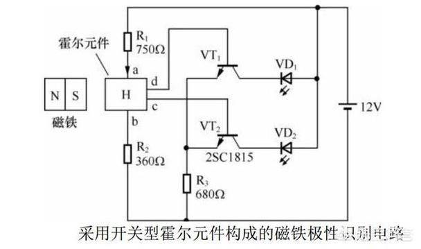
Hole integrated circuits can be divided into linear and switch types by output, and bipolar and mos-types can be divided into active units within integrated circuits. Figure 2 and figure 3 show, respectively, the theoretical and logical structure within the bipolar hole integrated circuit. Figure 2 is switch-type and figure 3 is linear。
In figure 2, the magnetic test of hole component h is reflected in the output of the high and low level of electricity. V1, v2, which amplifiers the power of hall, magnifies it by about a few dozen times; v3, v4, which forms the schmidt trigger, which transforms the contours of hole into a rectangular pulse; v5, v6, which further buffers the rectangular pulse; and v7, v8, which collects the electrode output tube for the open circuit. There are two output ends in figure 2a, where the icd output structure is used because it has a large load capacity and is easy to interface with different types of circuits, but some of the hole integrated circuits are in the form of launch polar circuit output, as shown in figure 2b, 2c。
Figure 3 shows the internal structure of the linear hole integrated circuit, whose output voltage changes continuously in response to changes in the strength of the external magnetic field, and its output curve is generally shown in figure 4. It is characterized by high sensitivity, dynamic output range and linearity. In figure 3a, v1 and v2 are differential amplifiers, negative feedback from r1 and r2 radio-extracts widens the linear range of circuits, and v5 and v6 second-degree differentials are magnified by a high multiplier. Some linear hole integrated circuits also set up out-end off-site connectors to compensate, turn zero or change circuit sensitivity。
Iii. Application of the hole integrated circuit
Hole's integrated circuit, characterized by no contact, no wear, no sparks, low utility, long life, high sensitivity and high frequency of work, works reliably and steadily in a variety of harsh environments. For the switch type, the basic application is to be used as an approach switch, e. G., for hall's no-touch switch, limit switch, direction switch, pressure switch, rotor schedule, etc., and linear holic can be used for non-exposure ranging, non-tangible bits, no-mart motor, magnetic field measurements, etc。
For switch-type holic, the output end is generally in the form of a transistor tube or a circuit launcher, so that it can easily connect to loads such as direct-drive transistors, leds, pv couplings, one-way two-way transistor tubes and small current relays, and can interfaces with ttl and cmos digital circuits, plc input portals, solid state relays, and various direct flow electronic switches. Figure 5 ~ figure 6 illustrates the various modes of driving the interface, with holic in figure 5 for the opening electrodes and with holic in figure 6。