Boost-voltage circuit principle, action analysis - kia mos tube
Boost-up circuits are one of the six basic cutting-off circuits, a switch straight-flow-up circuit that allows output voltage to be higher than input voltage. Mainly applied to direct current motor motion, single-phase power factor correction (pfc) circuits and other direct current power sources。
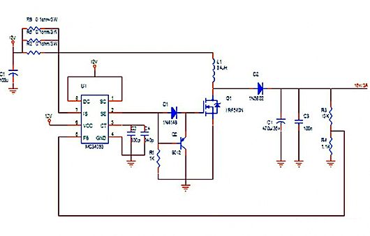
Usually, switch q1 transmits the sensor energy, capacitating c power, generating negative right-right positive electric motion after switch m1 has been shut down to enable the diode catheter to operate and power。
Boost transformations are also commonly referred to as voltage conversions, electrons l storage, which achieves the aim of boosting the pressure by channeling and off the m1。
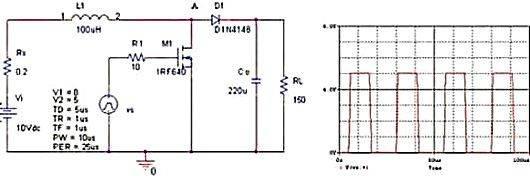
When the switch pipe is activated, the power is generated by a sensor - the switch tube forms a circuit, and the current is converted into magnetic energy storage in the sensor; when the switch is disabled, the magnetic energy in the sensor is converted to an electric right-hand positive on the left side of the sensor, which is stacked at the right end of the power source and is formed by a backway via the diode - load, which completes the lifting function。
In this case, the efficiency of the conversion has to be improved in three ways:
1. Minimize the resistance of the turn-off circuits of the switch pipe and enable as much electrical energy as possible to be converted to magnetic energy;
2. Minimize the resistance of the load circuits and enable as much magnetic energy as possible to be converted into electrical energy, while minimizing the loss of the circuits;
Energy consumption needs to be minimized, as circuit conversion is not meaningful and cannot be supplied。
Boost-up circuits
When the switch is disconnected, the energy stored in l is discharged to the load via a diode tube; at the same time, vi is also discharged to the load via a diode tube, superseding the two to achieve boosting pressure, dt = (1 to space ratio)* switch cycle= (1-d)*t。
During the two periods of shut-down and disconnection, the electrons charge the same amount of charge as the discharge, which is described by some as the spectrospective properties of the sense, which are, in fact, all the same in nature, beyond the process of charging。
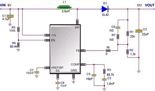
Boost-up circuit function
For a solar grid system, both time and weather can lead to changes in sunlight radiation and the voltage of its power points will change. In order to increase the amount of electricity generated and ensure that solar panels are capable of delivering the highest power in times of weak and strong sunlight, a boost-up system is usually added to the reversers to widen the voltage of their work points。
Contact information: mr. Zou
Contact: 0755-83888366-8022
Mobile: 18123972950