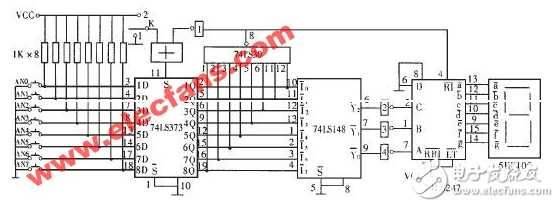
Eight-road pick-up circuit iv: a simple eight-way pick-up circuit
Detailed circuit design: eight-road pick-up circuit figure
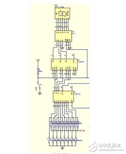
Eight-road pick-up circuit design option v: eight-way pick-up based on 74ls148 and 74ls297
Design requirements and content
In many competitions, in order to determine the first responder accurately, fairly and intuitively, a answering machine is usually set up to indicate the first responder by a number of means, including light, light or sound。
(1) designed and prepared a digital answering machine to accommodate eight teams, each setting up a pick-up button for the responder。
(2) the circuits have the capability to identify and lock first-hand signals. Following a pick-up instruction from the host system, if the contestant press the grab switch, the group signal lighted and the circuit was shown in group to show the group of the caller, while the light (lighted diode) was lit. At this point, the circuit should have a self-locking function, which would render the pick-up switch for groups ineffective。
(3) if the time limit is not answered, the alarm light shall be extinguished。
Grab the circuit
The main function of this part of the circuit is to enable the 8th tracker to pick up and lock, with corresponding lighted diodes and digital displays。
Use priority encoder 74ls148 and locker 74ls297 for completion. The circuit has two main functions: first, to identify the number of the player's key and to lock the number of the first responder, while the code displays the number of the circuit (which shows the circuit using seven digital displays); and second, to prohibit other players from pressing the key, which is invalid. Work process: when the switch s is placed at the " clear" end, the r and s ends of the rs triggers are zero, four triggers output zero, leaving the 74ls148 priority coding working mark = zero working. When the switch s is placed in "start", the answering machine is waiting to work, and when a player presses the tick button (e. G. Press s5), the output of 74ls148 is locked through rs, ctr = 1, rbo = 1, 7 shows the circuit 74ls48 working, 4q3q2q = 101, and the code is shown as "5". In addition, ctr = 1 to keep the 74ls148 priority encoding task marker = 1 in a prohibited state, blocking other key input. 74ls148 is still a priority coding mark = 1,5 because it is still a ctr = 1, so 74ls148 is still in a inhibition state, ensuring that the signal is not entered when the second key is pressed, guaranteeing the priority of the answering person. As long as a group of athletes press the answering machine first, the encoder is locked to death and no more other groups are coded. Displays 0-7 for the grab group by 74ls48 transcoder. If you have to reset the s switch by the facilitator, then you will have to reset the s switch and then go to the next round。
The rationale is as follows:
Countdown and alarm circuits
The rationale is as follows:
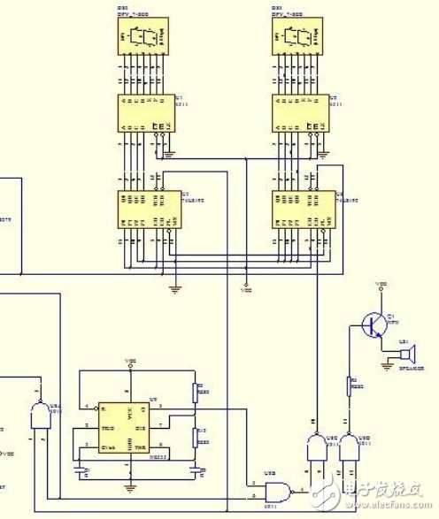
The component consists mainly of 555 timer seconds pulses that generate circuits, 74ls192 reduction array circuits, 74ls48 code circuits and 2 7 segments of digital tubes, i. E. Associated circuits. The completed feature is a 30s countdown when the host presses the start of the answering button, and a countdown light is activated at 0s. When an answer is sought, the timing stops. Two 74ls192 achieves the reduction count, which is displayed on the digital tube through the coded circuit 74ls48, where the clock signal is provided by the clock generating circuit. 74ls192 pre-set control end achieves a pre-set number of 30s, and the clock pulse of the counter is provided by a second pulse circuit. When the key starts, the counter starts counting and shows the time on the seven-part digital display tube in the cathode, stops counting and shows the countdown time at this point when someone is answering; if there is no answer and the countdown time is up, output the low-to-time level to control the circuit, control the alarm circuit, and invalid later。