Technical protocol i on rectangular steel tube concrete structure
Step 1.
General principle 2.
Terminology and symbol 3.
Material 4.
Basic design provision 5.
Structural systems and analysis 6.
Reconstructor design 7.
Node design 8.
Anti-side components design 9.
Design 10 for the turbo.
Fireproof design 11.
Appendix text indicates the scope of application of the protocol
1. Special requirements for the design and construction of rectangular concrete structures applicable to industrial and civil buildings and general constructions. 2. Construction of heavy structures without consideration for the direct bearing of power loads. 3. Except as specified in the present protocol, the design of concrete structures with special design requirements and exceptional circumstances shall be consistent with the design of rectangular steel-coated concrete structures with special design requirements and, in exceptional cases, with relevant national standards
Iii.
Element 1. Steel: q235, q345, q390, q420(1)q235a-class steel should not be used for welding structures (2) rectangular steel tubes with a cold bending straight or spiral welding welding to take over the the thermal pipe cold bending steel or thermal roller steel plate, thermal roller steel welding to the bar 2.
Basic design provisions
1. General industry and civil construction safety levels are desirable at level ii, design life of 50 years
2. Multi-high-level anti-side structure is the steel structure that moves between the lower layers of wind loads by more than 1/400 earthquakes by 1/300 earthquakes 1/50
3. The αc work absorption factor for concrete in rectangular concrete components (1) the smallest side of the transect 100 (2) the thick side of the tube wall 4 (3) the high width 2 (4) the pressured components should be (0. 1 ~0. 7)
(5) weld embolisms, etc., at 800 on the largest side of the section (6) wall thick axle pressure
Bend
Bend
(7) at the time of the construction phase test, the above limit values shall be divided by 1. 5, and in form fy
Replace it with real stress. Five.
Structural system 1. Structure system and maximum applicable height
Non-earthquake 6o 7o 8o 9o frame 1501109050 frame - steel support (inlined shear wall) frame 260220200140 frame - concrete shear wall, frame - concrete core drum 24002199015070 frame, cylinder 3603002601802 rectangular concrete frame frame - steel beams or steel concrete beams may also be used, steel slabs or collages 3 anti-side structures steel support, steel slitting wall, inner steel support r. C. Shear wall, steel shear wall or shear wall wall
Building beams: steel-concrete combinations or non-combined beam panels: pressured steel plates are now mixed or non-combusted, integrated floors, prefabricated plates or other light floors 5.
Reconstructor design
1.
Axis under pressure (1) strength
(2) stability
Calculating,
2. Axis pulled
N≤asf/3. When the convulsion (1) (intensity (2) (corresponding) is stable inside the plane (3) the concretization stabilizes the non-earthquake combination outside the plane, when there is a combination of seismic effects, the pull component 5. Double-directional bending annex
Strength: stabilization: x-axis around the main axis: y-axis around the main axis: 6. The longness of the two-way pull convulsion component 7
Is a strong column coefficient. General take 1. 0
For a framework of more than six layers, 8 degrees for protection, 9 degrees for defence, 1. 39 for calculation and test (a)
Short column (b) long column 9. Calculation formula and test comparison (continuing) serial formula equal to (x*) difference (xii) theoretical value and test value of test value (xii)
Vii.
Node design
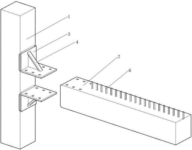
1. The sorghum connection node (1) rectangular steel tube concrete column and steel beam link (a) intersegment node (b) external partition interconnection note: 8 degrees defensive iii, iv site and 9 degrees defensive, it is advisable to use osteophysical connection (2) rectangular concrete pillar that is removed from the plastic sting (2) rectangular concrete pillar that is connected to the current sorghum node (a) ring beam + steel bearing heavy (b) retweaving (2) weak components of the strong node are designed to be seismologicalally resistant, in addition to the strength of the node to be measured in accordance with the strength of the seismic assembly. (a) steel beams and column nodes to fight: shears: shears derived from gravitational loads representation shall be calculated at nine degrees in a condensed beam and shall also include vertical seismic loads. (b) current beam and pole connections
Fight the bend:
Countercut:
More than tectonic requirements and design formulas 2. Cluster (1) welding at different wall-heavy plants (2) field welding at steel pipes (3) the width or height of the transects of two steel tubes is significantly different (a)s
25 mm
(b) 25
50 mm (3) clear differences in width or height of transects in two segments (continued) (c)s
>50mm3. Pillar foot (1) outsourced
3. Feet of column (continuation) (2) intrusion (dividation depth (2-3) cross-section height
(3) manifestation
Shear resistance: friction conveys, steel transfers with an anticipient key.
Anti-side component 1. Support (1) centre support with detailed design requirements
Single- and multi-layer can be supported with flexible centres, non-shock resistance, 6, 7 degrees, 8 and 9 degrees, single- and multi-layer support with presses, non-shock resistance, 6, 7, 8, 9 degrees, upper-level rigid support, non-shock resistance, 6, 7 degrees, 8 degrees, 9 degrees, (2) eccentric support with high-order design
2. Tectonic requirements and design formulae for the steel plate shear wall
A formula for measuring shear strength and stabilization: no hard ribs: strong ribs:
3. The concrete shear wall with a frame concrete consists of a reinforced concrete shear wall with a rectangular steel pipe concrete column and concrete beams ... With a horizontal and vertical load ... Structural analysis: rectangular steel pole concrete column may be converted to a concrete column as a single concrete pillar as part of the overall analysis of the shear wall wing wing ... It may be assumed that the full bend and partial vertical load ... Concrete beams are considered to be structurally irrelevant ... The shear wall bears the full shear and partial vertical load ...
Design of the frame
1. Rectangular steel condensed concrete frame (string is rectangular steel condensed concrete) (1) the length of the calibration pole is calculated using a string bar on the inside of the frame plane in the abdomen pole on any plane (2)t,y,k,n,x nodes on the line, and the abdomen are not allowed to penetrate the pole internal
Type k or type n should use a gap between abdomen g>0, g should satisfy:.
Design of the frame
(continued) when the k-node or n-node uses a connector, it is advisable to use the tp as shown in figure 9. 2. 6. 1, which should not be less than twice the thickness of the abdomen。
When the demand is not met by the greater arc of the abdominal pole and the nodal anti- pull load is not met, measures enhanced by steel plates, as shown in figure 9. 2. 6-2, may be taken to enhance the size of steel plates to meet the following requirements:
Nine.
Design of the frame
(continued) when the axial force of the abdominal pole is greater and the nodal anti- pull load does not meet the requirements, measures enhanced by steel plates, as shown in the figure, may be taken to enhance the size of steel plates to meet the following requirements:
Nine.
Design of the frame
(continuation) welding links between the abdomen and the bar shall be welded continuously around the abdomen and smoothly transition. The welding of a bellow and a string bar may be based on an angular welding, in part by an angular welding, in part by a welding; and a welding of a welding of a welding or an angular welding of a welding of a welding of an abdominal tube with an angle greater than or equal to 120°. The welded foot size of the welding welding between the abdomen and the strings should not be twice as thick as the wall of the abdomen or twice as thick as the wall of the abdomen. When the abdominal pole is equal to the width of the string pole and welding at the mouths of the horny slope as shown in figure 9. 2. 6-3, welding is assessed to ensure the quality and strength of the welding。
Nine.
Design of the frame
(continued) (3) welding length of abdomen and string poles of t, y, k, n, x
The actual length of welding in the pressurized abdomen; the effective length of welding in the abdomen
T, y, x nodes
At the time..
At the k-n gap point
It was nine.
Design of the stand (continued)
(4) t, y, k, n, x node design formula t, y, x node
The pressured abdomen node is designed to carry the following values:
Nine.
Design of the stand (continued)
Design values for the carrying capacity of the abdominal node are calculated in the following manner:
At the time..
At that time, take down two smaller values
Nine.
Design of the stand (continued)
K, n node
The pressured abdomen node is designed to carry the following values:
Design values for the carrying capacity of the abdominal node are calculated in the following manner:
Right now
When, but less, take down two smaller values
Nine.
Design of the stand (continued)
2. The steel plating and the assembly plate (working together with the concrete plate) (1) analyses can ignore the cross-section area of the pressurized rod (2) the maximum length of the rod is based on the steel structure design code (3) allowing scratching = 1/500 (4) the anticiplining connector design x.
Fire-resistant design
1. The rectangular concrete pillar of the rectangular steel tube with a fire-resistant grade above the 3rd stage of the main load bearing structure is the column of rectangular concrete column with no fire protection coating and with fire protection coating
2. Fire-resistant thickness of 3. Fire-protected steel-coated concrete pillars with no fire-protected concrete columns is shown in the table (1) when the top of the pillar moves side by side
(2) when the top of the column moves sideways and the layer moves less than 1/50
Xi. Construction
1.
Production, construction of rectangular steel tubes.
Concrete construction should be done with a catheter.
Pipewater construction 4.
Pump up top and build 5.
Manual-by-part construction
Each methodology described: concrete-silver combinations with quality testing, etc