I. Maintenance of the first half of the printer print page without images
A hpkserjei laser printer often shows no images of the first half of the printed page, while the latter part is printed on the first half of the original, but the images are normal and non-conforming。
The failure indicates that it is caused by poor paper supply, which normally is not in a state of rotation but in a short state of suspension when the paper is rubbed between the top and lower balconies. When the controller receives a signal of the opposite sensor output in the scanner orbit, the balconies rotate, that is, the paper is sent to the motionful drum of the rotation, and the paper is sent at the same speed as the line speed of the motionful drum, the front end of the paper is matched by the front end of the image on the sensor drum, and then a printing page is printed and projected。
When the paper is sent in front of the tablet, if the speed of the paper is equal to the speed of the light drum, the page is the first half blank, with no image, while the second half is the first half of the original and the image is normal, otherwise the image is deformed。
As can be seen from the above, this is due to the problem of the opposite sensor or controller and the examination of the sensor on the frame of the orbital frame of the scanner. A sensor was found to have problems, resulting in an advance delivery of paper to the tablets, the replacement of the sensor and the test printing, and the failure was eliminated。
The scanner moves to the paper side and cannot return to the original hp laser printer, and during the continuous printing process, the scanner suddenly moves to the printer's paper side instead of returning to the original location, and the printer sends an unusual sound of “how”. The scanner could not return to its place of origin for the following reasons:
(1) return sensor performance is poor。
(2) the controller has poor performance。
(3) return to poor sensor control。
(4) mechanical failures in scanner drive systems。
Based on the phenomenon of failure, which occurred suddenly in continuous printing and was accompanied by an abnormal sound, the mechanical part of the scanner drive system is suspected of malfunctioning。
Switching on printers, moving scanners back and forth with hands, it is very easy to move scanners with hands, as a rule. To do so, the scanners are pushed back to their original position, they are opened and the panel shows normality, and the scanners start moving forward when the main electrical motor begins to rotate. The exposure light is not on, the scanner is moving without hearing the abnormal “how, how, how,” which most of the sound is when the scanner enters the end of the orbit and meets the rack. Under normal conditions, the main axle motor begins to rotate when the printer is preheated to a certain temperature, and if the scanner is in place it remains static; if the scanner is not in place, it should return immediately。
The printer was opened, the hand-to-hand move scanner was checked further, and it was found that all the chains followed and, normally, the moving scanner frames were rotated only around drums with a scanner-driven wire line, which were not. This appeared to have problems with drums and drive chains, all of which were scanner-driven components, which were located on the inside side of the drums, which, under the action of the clutch, rotated the driving axis. Following a review of this part of the disassembly, it was found that the ball bearings of the wheel had been badly worn out, that the drive axis had been sharpened out of a slot, and that the chain wheel and the drive axis had been bitten to death, so that when the wheel began to turn, the drive axis was driven, and the drum wheel moved simultaneously, driving the drum axis “one direction,” leading to a malfunction in which the scanner could only move forward and not return。
In order to completely eliminate the malfunction, the replacement of a new clutch will result in the installation of other components in place for testing, normalization of work and troubleshooting。
Ii. Printers do not react when sending printing from software
There is a hewlett-packard laser printer which, when sending a printing operation from the software, does not respond to the printer for the reasons and the inspection exclusion method as follows:
(1) the power lines are not connected to the printer or the power is not connected to check the power and power connections to make them robust。

(2) printers may be suspended, dormant, software used to restore and awaken printers。
(3) the connection cable between the printer and the computer is not properly connected to re-establish the connection cable between the printer and the computer。
(4) the connection cable is defective: the cable can be tested on the normal machine to verify whether it is defective and, if proven to be defective, new cables should be replaced。
(5) the wrong printer is selected for checking the printer menu of the software to see if the correct printer is selected。
(6) the correct printer port is not available, the software configuration menu is checked to ensure access to the correct printer port and, if the computer is not a parallel port, the printer cable is connected to the correct port。
(7) printer connects to an incorrect converter and checks the converter settings, which connect the printer directly to the computer and then verify whether the converter is in question。
(8) printers should be repaired in case of failure。
Iii. Printed page as a whole light
A laser printer that prints out a coloured entire page. The causes of this failure are:
(1) there is no enough ink in the cartridge. Check the amount of ink in the ink cartridge and replace the inkbox or add to the ink powder if it is nearing the end of use。
(2) ink powder is sufficient, but concentrations are overregulated ... Toner concentration is re-regulated to make it fit。
(3) the light intensity of the sensory drums is insufficient ... Re-regulating the light intensity to make the light sufficient。
(4) the sensor drum heater is not working well。
(5) high voltage wire leaks, charging low voltage ... Checks if there are leaks, such as interconnections with fixed shelves, and should be treated insulated。
(6) a change in the location of the reprinter installation ... Checks whether the reprinter installation is changed and, if changed, adjusts the position to ensure that the reprinting voltage is sufficient。
Iv. Cards in the output paper section
A canon laser printer, whether printing large or small sheets of paper, is contained in the output paper section. The cardboard box is normal, only one piece of paper is covered, while the paper box is covered。
When the machine is opened for inspection, it can be seen that a single piece of paper passed through the two paper wrapper pieces of the output part without moving forward, while the lower cardboard box was stuck in the front of the paper clip of the output part, where more than one piece of paper was stuck. The explanation of the gap between the paper wrapper and the paper slipper, the lack of access to paper and the friction between paper slipper and paper slipper, which led to the discontinuation of the paper, is the result of the permanent appearance of paper cardboard, which caused the retorture of the spring on the paper wrapper, resulting in a lack of paper capacity in the paper wrapper, the inability to create friction between paper and paper slipper, and the fact that paper can pass through the paper slipper without progress。
Touch paper racks, loosely deformed, paper racks unloaded, replaced with a new spring, refilled, test-printed, back to normal and malfunctioning。
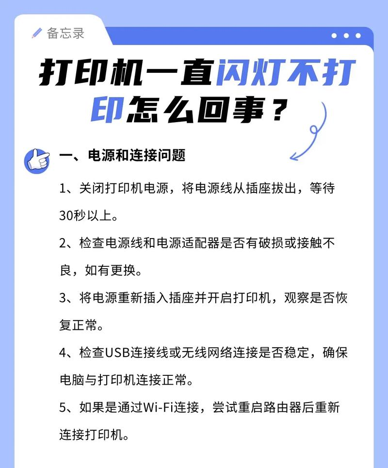
It is not clear whether you have encountered a situation in which the printer has not responded to a printing order issued through software。
So how do we solve this when we actually do this in practice? I hope that what follows will help you。
First, check whether the printer is currently set to " pause printing " , and if so, the printer will certainly not accept a printing order, no matter how it is sent to the printer. If the printer is able to accept the user's response, you can cancel the " pause printing " setting; when this setting is cancelled, you can open the printer operation window and then click on the program icon for the printer installed in the current system with the right mouse button, and you can see a tick in front of the " pause printing " command from the popup shortcut menu, and if you click this command option again, you can cancel the " past printing " setting。
Check whether the computer-connected printer has been set as a default printer. Since in many windows programs, when clicking on a " print " command, the program transmits the currently open page content to the default printer, if the printer used by all is not previously set as a default printer, the print content cannot be sent to the currently installed printer and the document cannot naturally be printed。
At this point, you can open the printer operation window and click the corresponding printer icon with the right mouse button, select the " set as default " command from the short menu that you then pop up, and set the printer to the default printer for all windows programs。
3. Check whether the printer is on-line and, if the printer is not on-line, the printer is naturally not operational. To keep the printer on-line, it is important to ensure that the printer's power is connected, that the printer's power switch is open, that the printer's paper is properly placed, that the ink, cartridge or colour belt in the printer is valid and that the current printer does not have a cardboard phenomenon。
The most direct way to see whether a printer is online, of course, is to see whether the “online” light on the printer control panel is on。
4 check which port the current program is going to use for the printer. The check can be done by clicking on the windows desktop, then click " start " / " set " / " control panel " / " printer " , then find the printer icon in the printer window that is opened, and then click it right on the " properties " command in the shortcut menu, click the " detailed information " tab in the popup printer properties dialogue box, and check if the printer has been set up to the appropriate printing port under the " print to the following port " settings on the tab page。
Methods and techniques for checking common parts for printers
Printers are common office equipment and include mainly needle printers, inkjet printers, laser printers, etc. At the same time, printers are a malfunctioning office equipment, and the maintenance of printers is essentially the maintenance of their damaged components, so the detection and maintenance of the various components of printers will undoubtedly be of great importance to our maintenance efforts. The following is a description of the methods and techniques used to test the maintenance of common printer parts, which, it is hoped, will be of some assistance in the maintenance of printers。
I. Inspection of needle headers
When a needle printer fails, most results from a head break. Aqueous alcohol can be used to clean out needles, most of which are caused by needle breaks or, if not, by other failures, such as the breaking of signal lines, the burning of needle rings or the congestion of needle-guided holes. When a broken needle occurs, it is replaced and continues to be used。
1. Needle exchange methods for several generic printers
(1) lq-1900k/lq-1600kiii/lq-1600k4 header
Lq-1900k/lq-1600kiii/lq-1600k4 printheads consist of a double-layered needle organization, with two sizes of 12 each, with a length of 36 mm and a length of 26 mm. The 24 needles in the head of the printout are odd, double-column. From the directional plate in front of the header, the left is an odd number and the right an even number. The needles are: 2, 6, 10, 14, 18, 22, 3, 7, 11, 15, 19, 23, 4, 8, 12, 16, 20, 24, 1, 5, 9, 13, 17, 21。
First, the needle breaker test program checks out which needles are malfunctioning, then cuts the printer's power supply, removes the color belt box, unloads two pinhead fixed screws with a cross screw knife, squeezes the heat sheet (i. E. The shell) from both sides of the head print, and gently lifts the head up to see two attached soft flat cables, which can be pulled out. To wash the ink in front of the printing head and check if there is a needle shortage。
In the case of broken needles, an exchange of needles is required. The needle exchange should be preceded by the preparation of tools consisting mainly of stings, blades, diamonds, steel feet, oil and printing headers (a tool specially designed to disassembly the printhead). First, two screws of a fixed needle kit and a dispersor are removed with a cross screw knife, and the dispersing tablets with a special tool can be seen with several layers of structure on the head, and the needle is exchanged in the following order:
1) draws down the head of the print head, removes the triangulation of a fixed top and bottom printer, removes the top back of the copper cap, and shows the 12 long needles distributed around the line, differentiates between long needles or short needles from the results of the test, then determines the location of the broken long needles, removes the broken needle from the side; if there are short needles, removes all the long needles, then separates them with blades below the middle yellow copper mat, shows 12 short needles and takes out the broken needle in the same way. Then a good needle is removed from the printing head (depending on whether the needle is broken) and the length of the needle is accurately measured by the steel ruler, and the fresh needle is sharpened with a glass of gold in its size (note that the hair of the head of the needle is sharpened) and inserted from the original position. When the end of the 12 needles is lightened by hand, and the needle is recovered from the steering board in front of the head of the printing, it should be seen that there is a needle in the position of the pins no. 1 and no. 24 and that there should be a hole between the needles in each column and the needle, and that, if the position is wrong, it must be readjusted. At the same time, when the finger is released, every needle is recovered and every needle that comes out of the needle is given. Close the copper seat and be careful that before closing the copper seat, each needle must be placed in its slot。
2) test the flexibility and consistency of flight distance of each needle by pressing the upper circle (i. E., the long-cline circle) together with the base (corone seat) upon confirmation that all the short needles are in place, with a direct current voltage of a set of +10vs applied to each group of needles (which should normally be less than one second of the charge, or a pulse voltage on the online circle). In order to avoid returning to work after you have installed a top print needle (long needle group)。
3) installation of upper needles in the original order. The long needle layer locator is fitted together with the coil, and the needle can be installed when there is no gap on the side. The needle shall only be inserted in the position of the corresponding hole. From the tail to the head, the needle passes through several guidance slots, and the top hole is easily inserted. The second chute is a little more difficult, as it passes through, and the needle is easy to reach its position, and it also presses the tail of 12 needles with its finger. The needle should be found from the steering board in front of the head, indicating that the needles that are exchanged are good. After full insertion, check that each long needle's positioning sales must fall inside its trough and close the rear copper cap, at which point it should be seamless from the side. Finally, triangulation claws will be fitted with dispersors and tested on the original printer after confirmation that +10v power check needles will be used in the test method。
Before testing, do not install colour belts, and print a single sheet of paper for self-checking, in case of new needles. The test is then carried out using the print needle test program, which can be put into operation once it is established normal。
(2) ar-3200/ar-3200ii/cr-3240ii print header
The printing head structure of the three needle printers, ar-3200/ar-3200ii/cr3240ii, is essentially the same, except for the three printing needles, which have a single layered structure with a length of 35. 2 mm, with the exception of the three printing needle springs, which have a different bullet power and a print needle-drive resistance。
The examination of needle breakers is the same as the above-mentioned epsonlq printhead. The exchange of needles takes place as follows:
1) the head of the printing head will be down, the black plastic shell of the printing head will be removed, a working font pad will be removed from the print head, and two metal-fixed cards will be removed by hand, followed by a rear lid, a pin-coated iron-pressed spring and a white plastic frame, so that the corrugation of the 24 needles in a row can be seen。
2) take out a broken needle with a stubble (when a stubble is used, act lightly and do not bring out the nylons and record springs under the print needle), similarly remove a good needle from the head of the print needle, measure the length of the needle with a precise size of a metre, press the new needle to the size of the needle, and then insert it from its original position after grinding it to the hair of the needle, with a light finger on the cortex of 24 needles, to expose the needle from the steering board in front, and to see if the 24 needles are all out。
3) when the white plastic stand is returned in the original order, the printed pin-coated iron spring, the rear panel and the fixed card are loaded with the printed head casing, and the drive circle (the method is the head of the lq series) is applied to each group of needles with a set of +10v direct current voltage, and the flexibility and consistency of flight distance of each needle is tested in the sequence。
4) the printing header is returned to the original printer, without a colour belt, and is then tested in a printhead test program after the self-checking of a single sheet of paper (in order to prevent the suspension of the colour belt by newly loaded needles), which is then available after a normal check。
2. Inspection of needle coil failure
Another common malfunction in the headline is the damage to the drive wire. The method of determining whether the drive wire has been damaged is to insert one end of a print head cable into the head of the print, and to measure the direct current resistance of the other side of the drive circle with a single scale, the direct current resistance of the general drive circle should be 33 euros ±2 euros, which, if the difference in the observed resistance is greater, may be the opening of the wire or a short circuit, which could lead to the failure or weakness of the needle. One of the tables can be replaced with the common end and the other with the corresponding points of the drive wires, and the individual wires can be replaced by removing the welding from the wires with a suction and cutting off the adjoining glue with a blade。
Most of the reasons for the failure of the print drive wheel were the damage to the needle drive on the main plate. Drives are hit through short circuits, causing the drive to be too large and the wheel to burn. To determine whether the drive is faulty, the print head cables can be measured on a single scale: the red pen to the public end (the public end is the driving power pole) and the respective positions of the black pen to the drive. When normal, direct current resistance should be measured at around 18 000 euros, indicating that the driver has been damaged if the deviation is greater. Each drive corresponds - a single printer, such as 24 drive tubes q1 ~ q24 on the main board of lql600k printer, corresponding to a printer of 1-24。