An analysis of the main axle structure and the working state of the hydraulic system led to the non-attendance of the main axle because of the high temperature caused by the less efficient operation of the hydraulic system, which led to excessive discharges in the sowla knife hydraulic tank, affecting the operation of the swirl; the improvement of the system by means of double pressure, double flow control of the oil pump and online monitoring of flow sensors to achieve system targeting to meet the different hydraulic loads of pressure and flow requirements; the verification of the operation of the machine bed, which resulted in a marked improvement in the efficiency of the operation of the new system, a significant reduction in energy consumption, a reasonable increase in the temperature of the fluid, an effective solution to the problem of the main axle acetone, and the introduction of prejugation of the failure of the swirler to improve the overall efficiency of the machine bed。
1. Preamble
The core component of the main axle, which is attached to a numerically controlled blade, and rotates, has a significant practical value and broad application prospects for failure analysis, debarment and prognosis of the main axle, because its stability and reliability directly affect the safety and processing efficiency of the machine。
2. Fault phenomenon
The main axle blade was released after several hours of cyclical operation of a certain number of control machines, which caused the machine to lose normal exchange of knives and to call the police to stop work; however, the power outage took several hours before it turned on and the machine bed returned to normal. This failure seriously affected the processing efficiency of the plant's production。
3. Analysis of causes of failure
3. 1 structure characteristics of the main axle sura
As shown in figure 1, the main axle of the sura blades was released and tightened to move in different directions through the hydraulic tank pistons and rewinding. When the spring is in a state of compression, it is installed inside the lifting apparatus, when the main axle needs to untie the blade, when the high-pressure oil enters the cleavage cavity, when the piston reaches out and pushes the piping rods away from the cone of the main axle, when the bow spring is further compressed and the blade is released; when the blades need to be tightened, the piping oil enters the piping cavity of the piping, and when the piping is required, the piping is pushed back into the cone of the main arc, and the piping of the pedestal is pushed by the cedure in the repo。
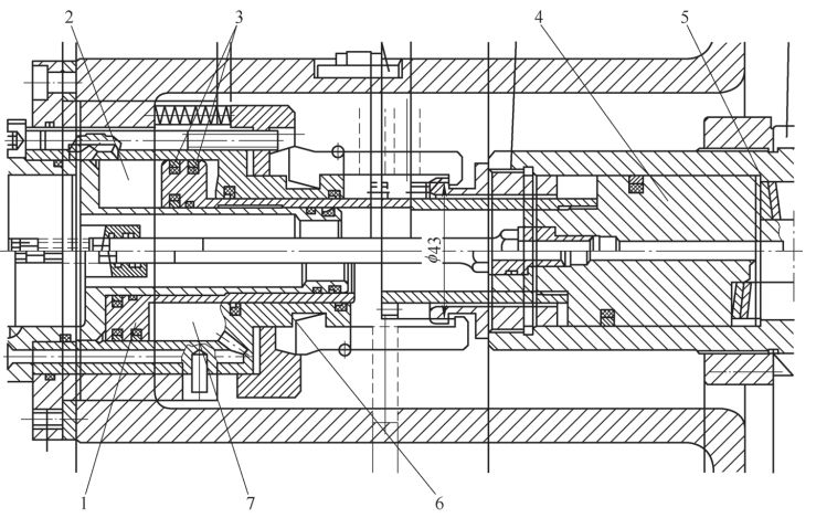
Figure 1 structure of the main axle sura
Pistol 2-piston cavity 3-cyper-cyper 4-ride 5-red 6-pistol 7-run-cyper
This machine-bed swirl requires a push of 14-16 mpa, a push of 5-16 mpa and a flow of 4. 5 l/min. When a pine knife malfunction occurs, even if the pressure of the system is pushed up to 18 mpa, the failure remains, together with the intermittent release of the main axis, indicating that the cause of the failure was not caused by the death of the main axis's internal mechanical card, but that the temperature of the hydraulic station was found to be higher, which led to an analysis of the increase in the internal leak of the hydraulic cylinder piston as a result of the high temperature of the oil, thus affecting the conduct of the cleaver, and therefore the focus of the failure excavation was on the hydraulic station and its control circuit。
3. 2 original hydraulic system analysis
Figure 2 provides a brief picture of the control of the prototype hydraulic station and the main axle sura, in which the pump 1 is a pressure compensation variable pump, with a maximum output pressure of 21 mpa and a maximum flow of 21. 5 l/min, as pressure is required by other hydraulic implementing agencies, such as the knife bank and the switch, at a lower pressure (4. 5-5 mpa), so that the fluid is reduced to 5 mpa by pressure reduction valves for use by other meta units。
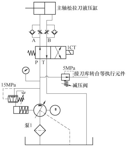
Figure 2
According to the method of operation of the pressure-compensation variable pump, the flow automatically decreases when the system pressure exceeds the assigned value of the pump, with the main axle pine knife shown in figure 3 at point a at the working point of pump 1 at point b at the working point of hydraulicly executed instruments such as the knife bank, the switchboard and so forth, and the pump 1 at point c at the operating body of the machine bed without hydraulic pressure, at which point the volume of flow depends on the internal discharge of the pump。
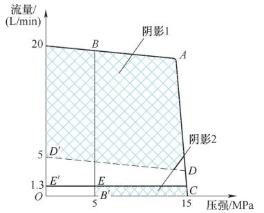
Figure 3 pump 1 pressure-flow curve
As can be seen from figure 3, when the main axle pulls a knife, pump 1 is unnecessary and useless in part 1 of the shadow, almost three times as useful as it is (figure 3 in the oddd' section); when the machine bed is on standby or when there is no hydraulic manoeuvre, pump 1 in part 2 of the shadow is equally useless and almost twice as useful (figure 3 in the ob'ee' section). As a result, system output pressure, flow and load pressure, as well as flow mismatches, have resulted in less efficient systems, and the failure to function has largely turned into heat in fluids and containers, leading to increased fluid temperature and reduced viscosity, leading to greater leakage within the main axle sowla knife pylons and to a failure to achieve normal laxation。
4. Hydraulic system improvement design
While system improvements can reduce excessive rises in oil temperature by increasing external temperature control equipment at hydraulic stations, they increase the costs of machine-beds and land area, and, more importantly, waste energy and increase carbon emissions. This paper thus addresses the problem by changing the hydraulic station and its circuit control method by in-depth analysis of changes in the machine-bed hydraulic load patterns, the relationship between the movement of loads and structural characteristics and usage requirements。
Figure 4 provides a simplified map of the improved hydraulic stations and control circuits, where the pump returns the load pressure by switching the valves back to the different control valves of the different stages of the variable pump, and where the pressure sufficiency (the difference between the system pressure and the load pressure) is controlled in closed loops, balancing system traffic supply and demand and reducing energy loss and system heat. Figure 4 provides two sets of pressure, two sets of traffic, 15 mpa and 5 mpa at high pressure, 21 l/min at high and 5 l/min at low pressure. The flow size can be set by the spin button, the pressure can be selected by the electron °ct powering, and the pressure-flow relationship is shown in figure 5。
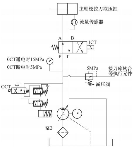
Figure 4. Summary of improved hydraulic stations and controls
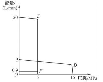
Figure 5 pump 2 pressure-flow curve
Point d in figure 5 is the pump 2 work point for the main axle pine knife, at which point the electromagnetic 0ct is powered; point e is the pump 2 work point for the machine bed during other hydraulic agency movements in a non-pine knife state, at which point the emt is not powered; point f is the pump 2 work point for the machine bed, at which point the electromagnetic 0ct is powered, at which point the visible pump 2 is less than the pump 1 standby pressure, at which the leak in pump 2 is clearly less than the pump 1, resulting in a lesser loss of non-essential power. Improved hydraulic systems, whether pump 2 is in any working or on-board condition, have output power which is essentially sufficient to meet the load demand without oversupply。
In addition, a two-way flow sensor has been added to the main axle cleaver circuit (see figure 4), which allows real-time monitoring of the total flow of fluid cylinders into or out of the fluids in the pine, cleavage and, when measured more than the normal quantity of oil, indicates that there is a larger leak in the cylinder and, conversely, that there is a mechanical death in the plume and lash, thus predicting the operational status of the main axle online。
Concluding remarks
Following the improvement of the hydraulic system, the machine bed has been operating over a long period of time and has been observed to maintain the temperature of the hydraulic station within a reasonable range, the temperature of the fluid has been effectively controlled, leaks within the pine, lash and hydraulic tanks have been significantly reduced and the reliability of the main axle pine and lash operations has been significantly improved. In summary, whether in the design development phase or in the upgrade phase, a numerically controlled machine-bed hydraulic system is required to select, based on an in-depth analysis of the real-time working conditions of the system, reasonable controls to maximize the efficiency of the system's operation, reduce non-essential energy consumption, reduce the volume of fluid heating and avoid various hydraulic malfunctions caused by the temperature rise of the fluid。