Paste metre devices typically include sticker resisters, sticker capacitors, sticker sensors, sticker diodes, sticker transistors and sticker integrated circuits. Welding methods are essentially the same for stickers, stickers, stickers, stickers, diodes, stickers, transistors, etc. The method of welding these stickers is described below。
Welded stickers
The sticker is generally more heat-resistant and can be welded with a hot wind rifle. When welding with a hot wind gun, the temperature is not too high and the time is not too long to cause damage to the adjacent device or to remove the element from the other side of the circuit board; the wind is not too large to avoid blowing or moving the adjacent object。
Welded patches are held in the following way:
1) first, the temperature switch for the hot wind rifle is moved to level 5 and wind speed is moved to level 2 and then the power switch for the hot wind gun is opened, as shown in figure 1-39。
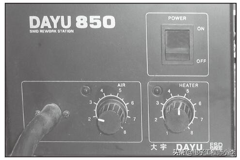
Figure 1-39 regulating hot wind guns
2) a sticker is attached with a tumbler, and the two ends of the resister are then directed to a small amount of welded tin ointment。
3) place the resistor in a welding position and then heat the heater vertically to the sticker, as shown in figure 1-40。
4) heated 3s, after welding has been stopped, and then welded by electric latte to two induced welds of components, as shown in figures 1-41。
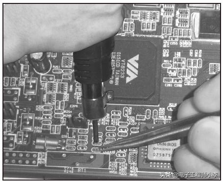
Figure 1-40 heated resisters
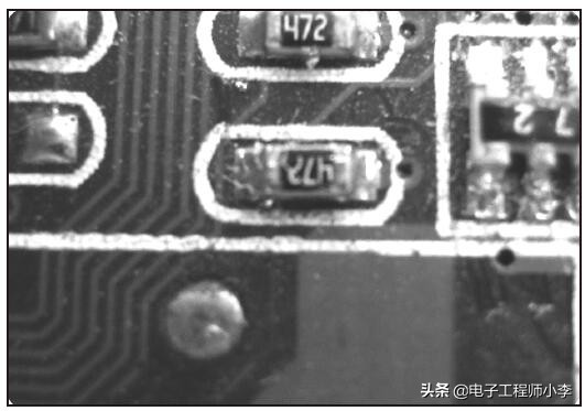
Figure 1-41 welded resisters
[stips]
Welding of stickers is generally free of electric latte, as welding is possible because welding of both welds cannot be melted at the same time; on the other hand, when the second welding point is welded, because the first welding point is welded, if the second welding point is pressed, it may damage the electrical resistor or the first welding point. When welding such elements, welding shall be melted with two irons and two welding points at the same time. The tip of the iron moves to the side to separate the welded point and then removes it with a hammer。
Welded patch capacitors
For general paste capacitors (surface colours of grey, brown, khaki, light purple and white, etc.), welding is the same as welded paste resisters, and reference is made to the paste resistor welding, which is not repeated here. Welding with a branded iron may cause damage to the capacitors when the upper surface is silver gray and the capacitors with a large, deep gray layer on the side, and other high temperature resistant capacitors. Welding is done as follows:
1) a small amount of welding shall be applied first to the two welding points on the circuit board and then to the welding point with the electric laminated iron, which shall be removed quickly when the welding melts, so as to smooth the welding point as shown in figures 1-42。
2) welding the capacitors properly and under pressure with a hammer, then welding them at one end with a branded iron, and then heating them with a branded iron at another weld, so that no pressure capacitors are allowed to damage the first welding point, as shown in figures 1-43。
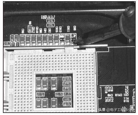
Figure 1-42, weld points. Tin
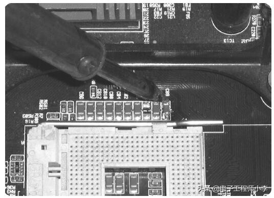
Figure 1-43 heating welds
[stips]
In general, welded capacitors using the above method are inappropriate and, if welded, welding points on circuit boards can be sequestered with a siphon wire and welded separately. If welding is less than possible, welding can be replaced with a little tin on the welding. If it is small, do not put welding on the welding point and heat it up to heat it up so as not to cause too much welding。
Welded tablet sensors
The welding method of the sticker is the same as the welding method of the sticker. Welding can be done by reference to the sticker welding method and is not repeated here. Figure 1-44 shows welded patches as sensors。
Welded paste diodes, transistors, field effect crystals pipe
Decorated diodes, paste transistors, paste field effect transistors are less resistant to heat, and need to be careful not to overheat and not for long. Welding is done as follows (for example, in the case of paste diodes):
1) first, the temperature switch for the hot wind gun is moved to level 5 and the wind speed is moved to level 2 and then the power switch for the hot wind gun is opened, as shown in figure 1-45。
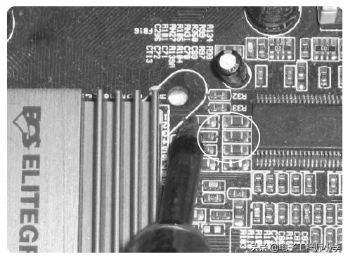
Figure 1-44 welded paste sensors
2) the two ends of the diodes are drawn to the soles of a small amount of welded cassiterite, as shown in figures 1-46。
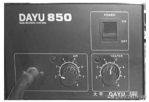
Figure 1-45 regulating hot wind guns
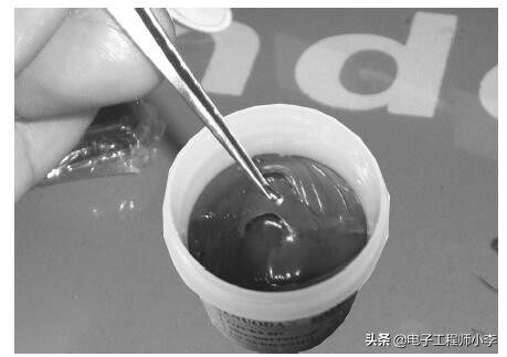
Figure 1-46 welded syd
3) place this device in a welding position and then heat it vertically to the sticker, as shown in figures 1-47。
4) when welding has been melted, welders are moved quickly and the heat is stopped, then welded with electric latte to the feet of the device, as shown in figures 1-48。
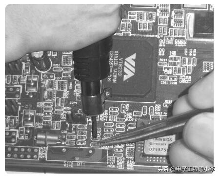
Figure 1-47 heated diodes
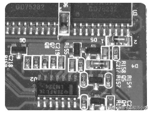
Figure 1-48 welded paste diodes
[stips]
When removing a device like this, use a hot wind gun. Straight to the circuit board is evenly heated and welded smelting is quickly removed with tatters. Since a slightly larger volume of stings has little effect on the heat wind, it is also possible to hold a metaware and raise it slightly upwards, while heating it with a hot wind gun can be separated when welding has just melted. Note the direction of the device before removing it and mark it on the chart as necessary。
Welding both sides of the toddler integrated circuit
Welding of integrated circuits on both sides of the pedal is as follows:
1) the temperature switch for the hot wind gun is first moved to level 5, the wind speed is moved to level 4, and the power switch for the heat wind gun is then opened. As shown in figures 1-49。
2) a small amount of welded tin ointment is applied to the lead foot of the attached integrated circuit。
3) welding of integrated circuits on panels with a sap and pressing, and then welding with a branded bar to form a guide to the circuit, as shown in figure 1-50。
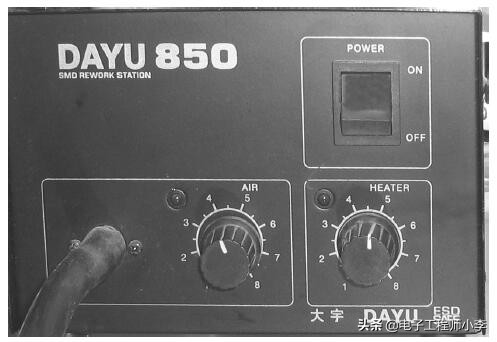
Figure 1-49 regulating hot wind guns
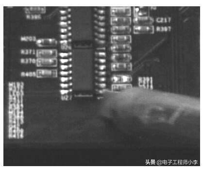
Figure 1-50 fixed integrated circuits
Attention
If welding on the circuit board is too high or too low, a little cedar can be used with electric latte and welding can be scraped。
4) the wind gun will then be reheated vertically to the attached integrated circuit, and will stop heating as soon as welding melts, and will be shut down, as shown in figure 1-51。
(5) once welding is completed, check for welding short-circuit lead. If yes, it is repaired with brand iron and welding is added to the attached integrated circuit, as shown in figures 1-52。
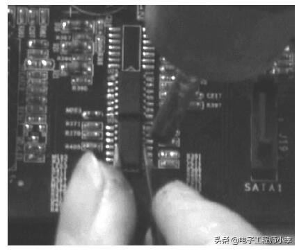
Figure 1-51 heating of an integrated circuit
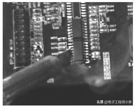
Figure 1-52 welding of integrated circuits tin
Welded four-sided toddlers and integrated circuits
The method of welding the integrated circuits on four sides of the pedal is as follows:
1) first, the temperature switch for the hot wind gun is moved to level 6, the wind speed is moved to level 3, and then the power switch for the hot wind gun, as shown in figures 1-53。
2) a small amount of welded tin ointment is applied to the lead foot of the attached integrated circuit。
3) welding of integrated circuits on the board with a hammer and pressing, and then welding of four sides of the integrated circuit with a barbed iron, as shown in figures 1-54。
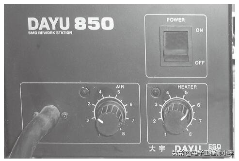
Figure 1-53 regulating hot wind guns
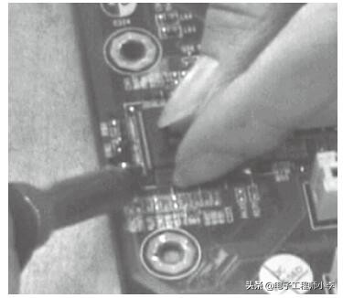
Figure 1-54 fixed integrated circuits
4) the heat of the hot wind gun is then reheated vertically to the adhesive integrated circuit, and will stop heating and turn off the hot wind gun, as shown in figure 1-55, after welding。
(5) once welding has been completed, check for welding short-circuit lead and, if so, repair it with a brand iron, along with welding for a patch of integrated circuits, as shown in figure 1-56。
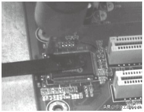
Figure 1-55 heating of an integrated circuit
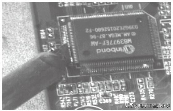
Figure 1-56 welding of integrated circuits tin