Installation of a current sensor (holl sensor) for abms cheng
Overview
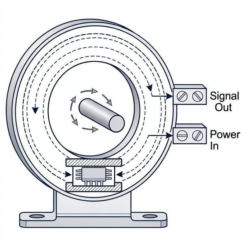
In the on-line monitoring system for accumulators, current sensors (e. G. Current sensors) are used to monitor chargeable currents in batteries and are key equipment for assessing battery charge state (soc) and health status (soh). Accumulation monitoring systems are now generally based on the open-ring (direct) principle hale current sensor, which has the advantages of being structurally compact, low-efficiency, low-cost, fast-response, and high intervention resistance. For example, the hole current sensor is used in this paper to provide details of its installation methods and attention。
Preparation for installation
2. 1 selection confirmation
Prior to installation, sensor models are identified according to the conditions on site and equipment specifications:
Open-to-closed selection: sensors have openings and closings. Closure accuracy is higher, but it needs to be installed with the ability to break the wires; opening is slightly less accurate but can be installed with constant lines. In retrofit projects that cannot be cut off, open sensors should be selected (the battery inspection system configuration is commonly open), taking into account the need to replace the sensors at a later stage of equipment maintenance。
Scheduling selection: selecting a scale that matches the actual current, with 1. 2 times the working current recommended. The passing of the scale has resulted in low accuracy and is too small to be damaged。
Equipping the environment: determines whether conditions such as the temperature, humidity, etc. Of the sensor's working environment meet the requirements of the equipment, with the normal hale sensor working at 25 - 70 °c。
Aperture matching: the current sensor that is close to the size of the cable or copper platoon is better measured and the conductor should, as far as possible, fill the sensor module aperture to obtain better dynamic properties and sensitivity。
2. 2 tools and materials preparation
Safety protection: insulation gloves, insulation shoes
Installation tools: insulation screwdriver, striper, wrench, bandage
Detection tools: universal meters, plier current meters
Materials: block communication lines (rs485), insulation tape, swelling screws or fixed racks (based on location of installation)
Related equipment: data acquisition module, monitoring mainframe, communication module, etc
2. 3 site survey and planning
The parameters for recording batteries: number of batteries, nominal voltage, total capacity, installation mode (box/frame)。
Identification of the location of the installation: the main circuit of the battery (which can be installed at positive or negative extremes, and is recommended to be installed at the general negative end to ease the wiring), to ensure that there is no shield between the sensor and the battery master or guide and to facilitate subsequent overhaul and maintenance。
Planning cable direction: avoid strong power lines, reduce electromagnetic interference, and reserve ventilating space。
2. 4 security precautions
The installation shall be preceded by a disconnection of the battery from the load or by the operation of a professional。
Wear insulation gloves and use insulation tools to avoid short circuits caused by direct contact of metal tools with the battery endpoint。
When using the hole sensor, the sensor's power supply and measurement end must be connected before it reaches the original side, otherwise the remaining magnetic impact accuracy may be created。
High-voltage batteries are required to cut off their electrical operation or to be carried out by professionals in strict compliance with the protocol。
Iii. Steps for installation of the current sensor (holl sensor)
3. 1 location of installation determined
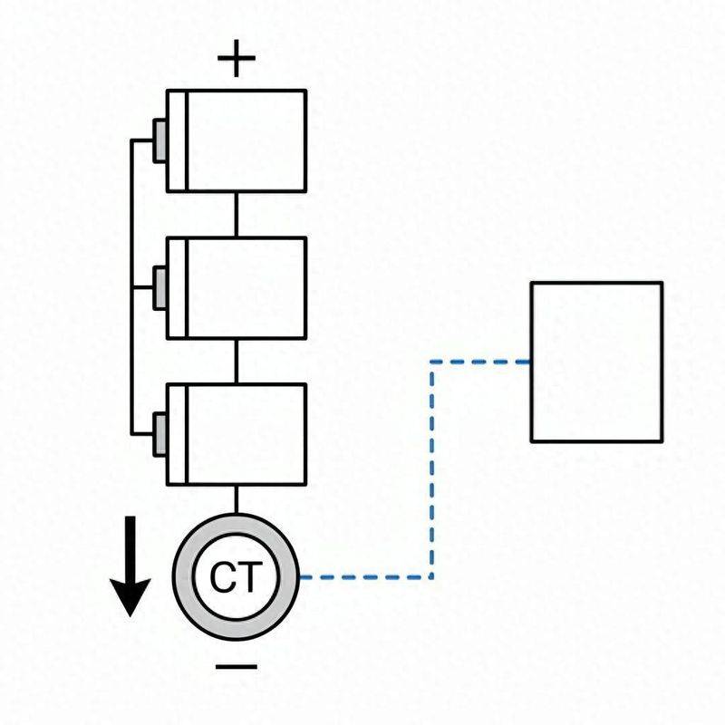
Hole current sensors can be installed on the main circuit of the battery at the main or the overall negative end, and it is recommended that they be installed at the general negative end, which is easier to walk and safer. Sensors are placed in the direction of the current: the arrow direction on the sensor should point to the direction of the current flow. Specifically, if the sensor is placed at the main negative end of the matrix, the top arrow of the hole sensor points to the overall negative end of the battery。
3. 2 closed-mouth sensor installation (for new systems)
The closed-mouth sensor structure is an integrated ring, and the original line of guidance must pass through the sensor hole in order to complete the measurement, and therefore needs to be installed where the main circuit has not yet been connected or is allowed to be disconnected:
1. Confirm that the system has been powered and the main circuit has been cut。
2. Passes the main circuit line or the parent platoon through the central hole of the closed-door sensor。
3. Ensure that the conductor's aperture is fully filled by the conductor and that the directional position is medium。
4. The sensor is fixed in the appropriate position (e. G., battery frames, inner walls, etc.) with a fixed frame or screw。
5. Power and signal lines connecting sensors。
3. 3 open-ended sensor installation (for retrofit projects)
The open-door sensors are divided into two and a half rings above and below, and need not be installed without a break in the main circuit, especially for project modifications that are operational:
1. Opening card buttons that open the sensor。
2. The sensor is attached to the detectable cable or to the parent platoon to ensure that the detectable guidance is located at the central hole of the sensor。
3. Closed sensor openings, buttons, and ensures that the sensor is closed。
4. Stabilize sensors in appropriate positions with bandages or fixed clips to prevent relaxation。
5. Power and signal lines connecting sensors。
3. 4 connective steps
1. Powerline connection: hale sensor usually requires auxiliary power supply (e. G. Dc § 12v, ±15v or dc 24v, depending on product specifications), with correct access to the positive and negative end of the power supply by product description。
Signal line connections: the output signal of the sensor (usually 420 ma, 05v or rs485) is delivered to the corresponding input port of the collection unit。
3. Wire code:
Power lines and signal lines recommend the use of shielding double-crowding to reduce electromagnetic interference。
Wires are fixed along walls or shelves to avoid being trampled or pulled。
Cable identification: all cables at both ends should be labelled clearly (e. G. "total current sensor signal" "total current sensor power source" etc.) to facilitate future maintenance and failure detection。
3. 5 system connectivity (in the case of typical structures)
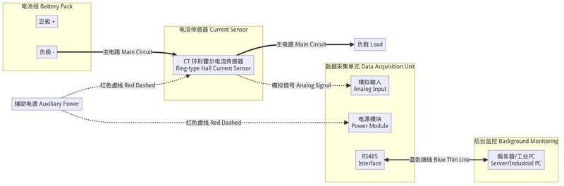
The current sensor is usually used in conjunction with the ta module (one-cell monitoring module), the tc module (cell monitoring module), interconnecting through the uart bus and receiving the yield module (data acquisition module), and accessing the back server through a serial or network portal. Sensor output signals are processed in the acquisition unit to display and record discharge current data in real time in the monitoring software。
Iv. Debugging and acceptance
4. 1 electro-testing
Check all wires without short circuits and when they are loose, connect the sensor power and observe the normal state of the indicator light, if any。
Activate a monitoring system to see whether current readings shown by the host or the software interface are substantially consistent with the measured values (symmetrically measured by a plating current table) and the error should be within the description of the device。
The measurement range of the original current of the sensor shall be in accordance with the actual condition and shall be capable of correctly showing positive (discharge) and reverse (charge) currents。
4. 2 warning verification
Reconciliation or simulation of current changes to charge, to verify whether the system responds in a timely manner and to record current changes data。
If the system has an overflow alert function, check if the current can trigger sound light or text message alerts when the current is overstretched。
4. 3 records and acceptances
Recording of sensor type, location, scale, direction, etc. For inclusion in the system document。
Ensure long-term system operations are stable and current data are non-jumping or abnormally volatile。
Once debugging is completed, the installation debugging records are organized and confirmed by the relevant party's signature。
V. Common issues and concerns
5. 1 precision issues
The failure to fill the sensor's aperture affects the accuracy of the measurement, and the installation should fill the central hole with a single guide。
Better dynamic properties and sensitivity can be obtained when the original and the sideline rings are well aligned。
When the measured current is well below the rated value, consideration may be given to the use of argon (i. E., multiple loops of the guide) to obtain a better measure accuracy, subject to the observation that the number of affixes does not exceed the rated value。
5. 2 environmental impacts
Avoiding the installation of sensors in the vicinity of a strong magnet or a large current carrier to prevent external magnetic field interference with measurements。
Where there is a stronger external magnetic field interference, this can be done by adjusting the direction of the sensor, adding a metal shield or selecting a double-hull component module。
Avoid installation in a high temperature gt; 70°c, climatizing wet or corrosive gas。
The temperature of the original feeder should not exceed 80°c。
5. 3 use and maintenance
Open-door hall sensors, although slightly less sophisticated than closed-door sensors, are more useful in retrofitting projects。
Periodically check whether the sensor is loose, the cable is ageing and is maintained in a timely manner。
When using the hole sensor, it is important to follow the sequence of “power-to-general currents” to avoid remaining magnetic impact measurement accuracy。
In the event that magnetic pathways are magnetized, remagnetized: in the absence of power from the subside circuits, the currents of exchange of the same grade size in the original locomotive are gradually reduced。
For applications that require monitoring of the chargeable two-way current of the accumulators, a sensor capable of supporting positive and reverse measurements (i. E., the quantities contain a positive and negative range) should be selected。
Summary
The quality of the installation of the current sensor (holl sensor) has a direct impact on the accuracy and system reliability of the data of the online monitoring system for batteries. The installation shall be preceded by adequate survey selection and tool preparation, reasonable selection of open or closed-door sensors according to the conditions on the ground, with strict attention to current direction, guide lines filled with apertures and wiring specifications, and post-installation debugging and acceptance. Strict application of the curriculum and safety precautions are necessary to ensure the long-term stable and reliable operation of sensors。