1 the use of plug-in valves as a single-way valve is shown in map 1 of the direction valves. Figure 1 (a) is identical to the normal one-way valve, controls oil cavity c-b connection, a-b single-director, reverse flow cut. Figure 1 (b) connecting to a for control of the oil cavity c, b and a single-guided, reverse flow cut. Figure 1 (c) corresponds to a liquid control one-way valve, which is a one-way valve function when the first control of the oil road k is under pressure (figure position); when the first control of the oil road k is under pressure, the control of the oil cavity c is out of pressure, which allows the reverse control of the b and the a。
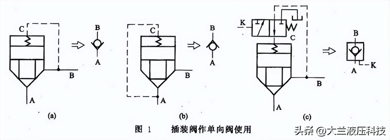
Insert valves for one-way valves
A small electromagnetic exchange valve is used to combine the lead valve with the plug-in valve and, through the control of the electromagnetic conversion valve, can be combined into a different common and digit switching valve. Figure 2 shows that two three-channel power-for-valve functions were formed for two plug-in components and a lead valve (two four-wire electromagnetic switching valves). The lead valve is out of power (charted state), the plug valve 1 is closed, the p vent is closed, the plug valve 2 has lost control cavity, and the a valve is open to o; when the lead valve turns through, the plug valve 1 has lost control cavity, the p vent is open to a, the plug valve 2 is closed and o is closed。
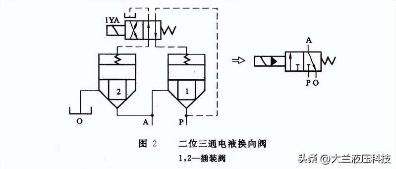
You two three-channel power to the valve
2. Plugged valves are used as pressure control valves with small direct spill valves as lead valves to control plugged components, and different control routes are used to form pressure control valves for various uses。
Figure 3 (a) shows spill valves consisting of pre-directed spill valves and plug-in components with a barrier to nicoons, which work in the same manner as the normal lead spill valves。
Figure 3 (b) shows the lead sequence valves consisting of plugins and lead spill valves for external interdiction of nicos. The working method is the same as the normal lead-order valve。
The plug-in valve core shown in figure 3 (c) is a frequent slide valve structure, with b being imported, a being exported, and a being connected with c cavity and precursor pressure valves through the internal barrier of a. When the pressure rises to or exceeds the calibrated pressure of the lead pressure valve at a, the lead pressure valve is activated, the slide core is moved up, the small valve is closed, and the control of the export pressure is of a given value, so it constitutes the function of the lead value impairment valve。
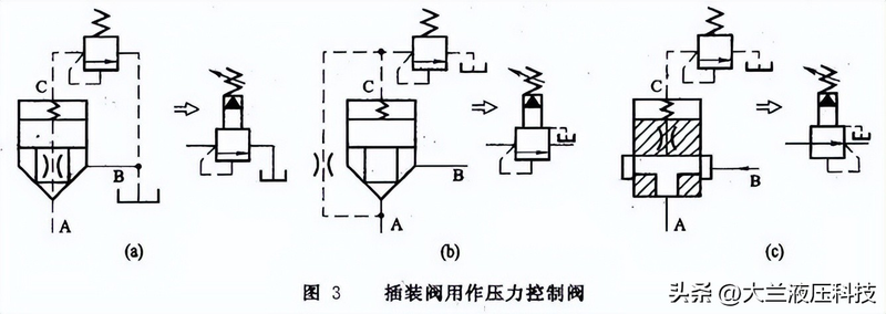
Insert valves for pressure control valves
3. The plug-in component used as a flow control valve has a shoulder tail at the lower end of the core of the cone and has a triangle or ladder strewn trough on it; and a processor (regulating screw) is installed on the control sheet to regulate the size of the flow of the core, i. E. The opening of the control throttle, and thus constitutes a throttle, as shown in figure 4 (a)。
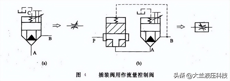
Plugging valves as flow control valves
The pre-plugged throttle is followed by an interpolated fixed-discharge reduction valve, which is linked to the import and export of the throttle at both ends of the pressure reduction core, as shown in figure 4 (b). As is the case with the principle of the normal repulsive valve, the pressure compensation function of the depressive valve is used to ensure that the import and export pressure differential of the throttle is essentially fixed so that the flow through the throttle is not affected by changes in load pressure。