In this paper, the grand lan hydraulic plant analyses the switch valves of the hydraulic system to the circuit。
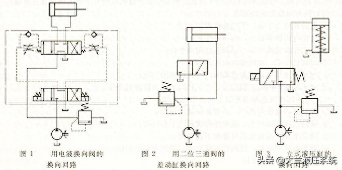
1 use of three four-ton electric fluids for the re-routing of valves, and the smoothing of circuits, as shown in figure 1, can be improved by regulating the throttle in the electro-prime valves。
2 the use of two-bit tri-valve differential hydraulic cylinders for circuital circuits and the conversion valves for electromagnetic valves, as shown in figure 2, has a larger impact, only in cases where the frequency of the switch is lower (under 30 times/minute), the flow is smaller (under 6 l/min) and the mobility component is less inertial。
Dalan's hydraulics turn back to the road map
A 3-tier hydraulic cylinder is converted using two three-way valves, which, as shown in figure 3, is a single-act tank using gravity or spring return。
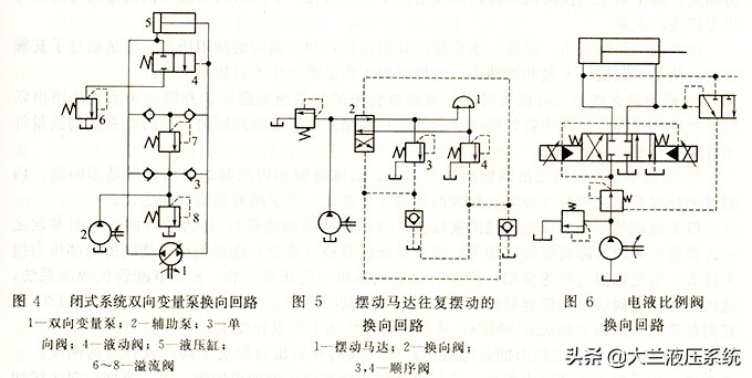
In a closed system, a two-way variable pump can be used to change the direction of the oil being delivered. As shown in figure 4, when the piston moves to the right, the auxiliary pump 2 supplements the oil by a one-way valve 3; the excess fluid during the reverse movement is discharged back to the tank by two-way three-way liquid motor valves and six spill valves controlled by the pressure of the inlet side. Spill valves 6 and 8 both prevent pump ingestion and stabilize piston movements; spill valves 7 are safety valves。
Dalan's hydraulics turn back to the road map
Note: this circuit is suitable for high stress and high traffic。
Five uses two four-to-four valves for swinging motor 1 to swing circuits, switching valves, as shown in figure 5, when the load pressure exceeds the adjusted pressure of sequence valves 3 or 4。
Noted problem: the re-routing of revolving valves is more precise and stable than that of pressure relays and electromagnetic valves。
6 the ratio of electron to valve-controlled circuits and, as shown in figure 6, the hydraulic tank is controlled by the ratio of electron-to-valve, which achieves both re-routing and velocity, and the differential pressure-relief valve provides pressure compensation for the main valve. This circuit control function is good and smooth and applies to situations where speed changes are slow and the mass of the motor parts is low。