This invention concerns distribution cabinets, in particular a distribution cabinet battery module replacement device and replacement methods。
Background technology:
1. At this stage, the 10kv distribution cabinet system is equipped with battery modules as backup power, which can still be used as a backup power supply for the short duration of the equipment in order to complete the necessary motion instructions at the time of the power outage. However, batteries need to be regularly inspected and replaced to ensure the proper functioning of the equipment, as their lifetime decreases gradually with the increase in their use time and may even be significantly reduced due to high temperatures。
At present, there are the following deficiencies in the existing distribution cabinet system when using battery modules as backup power: 1. Battery modules in the distribution cabinet system have difficulty purchasing batteries of the same size as the original plant's configuration in the face of the need to replace and expand batteries, resulting in the inability of the distribution cabinet system to comply with batteries of different sizes, models and capacity, thereby affecting the efficiency of the distribution cabinet; 2. The power outage of the distribution cabinet system is limited and requires that batteries be replaced quickly and accurately, reducing the difficulty and duration of battery replacement; 3. The temperature of the outer surface of the battery cannot be detected, resulting in the inability of maintenance personnel to replace malfunctioning batteries in a timely manner, putting the safe operation of the distribution cabinet system at risk。
Technical realization thinking
The technical issues to be addressed in this invention are: the inability of the distribution cabinet system to comply with batteries of different specifications, the difficulty of replacing batteries, their length of time, and the inability to monitor the temperature of the outside surface of the batteries。
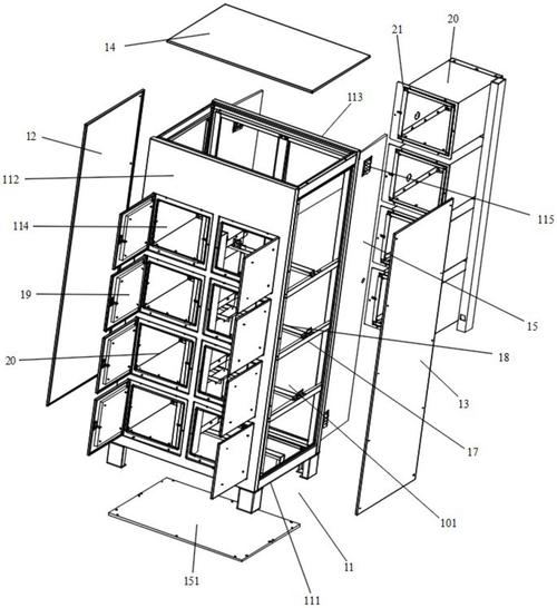
To address the above technical issues, the invention provided a battery replacement unit for the distribution cabinet, consisting of the box, the first limit assembly, the second limit assembly and the monitoring unit; the box consists of the bottom plate, the first side plate and the second side plate, which are set at the end of the panel in the direction of z, and the first side plate and the second side plate, which are positioned at the end of the panel in the direction of z, respectively, and the first side plate in the direction of x and the second side plate together to form the storage cavity of the cell module in the direction of x; the first side plate with the first side panel with the second slide along the direction of y and the second side of the first side assembly in the direction of the first side, which is used to monitor the movement of the first limit assembly at the end of the first side, and the second side of the movement module in the direction of the third side, which is used to monitor the movement of the first side and the second side of the movement assembly, which is used to monitor the movement of the second direction of the second column, and the movement of the second column to the second side of the movement of the second。
3. Further, the battery module includes the output and input interfaces for the transmission of electrical power to the distribution cabinet。
4. In one execution mode, the first limit component consists of the first block and the first fastening, with the first block being inserted at the end of the side plate in the first slide and the first hardening being set at the link between the first block and the first slide to fix the first block。
5. In one mode of implementation, the second dimension component consists of the second block and the second hardening, the second block plug is placed in the third slider and the second block is set at the end of the second block close to the first block for the fixed second block。
6. In one mode of implementation, the second dimension component consists of a third block and a third hardening unit, a third panel close to the second side of the panel is inserted in the second slide and the third hardening unit is set at the link to the third block and the second slide for the fixed third panel. The first, second and third slots are multiple and are set at z-direction intervals。
7 in one form of implementation, the moving components include the first slider, the first slider is set on the side of the second board deviating from the storage chamber in the direction of z, the first slider consists of the first plate, the second plate, the fourth compaction and the fifth compaction, with the fourth slide through the first plate, the fourth compaction is set between the first plate and the second panel and inserted in the fourth slide, the fourth tighter is used to fix the relative position between the first and the second plate along the direction of z, the second panel is set on the top of the first plate, the second plate is set up on the fifth slider running through the second plate, the fifth compaction is placed between the first and the second plate and inserted in the fifth slide, the fifth tightware is used to fix the relative position between the first and the second plate along the direction of z, and the top of the second plate is connected with a temperature control sensor。
8. In one execution mode, the moving component consists of the second skateboard, which is set in the direction of z on the side of the third block to deviate from the storage chamber。
9. In one way of implementation, the moving component consists of the third slider, which is set on the side of the side of the plate in the direction of z, the third slider, which is multiple in number, and the third slider, which is spaced in the direction of x and has the same structure as the first slider, the second slider and the third slider。
10. In one way of implementation, the end of the floor is also equipped with a handheld, which is used to facilitate the maintenance of people's mobile battery modules, and the bottom of the handheld is equipped with a link to the distribution cabinet。
11. In one way of implementation, the distribution cabinet battery module replacement unit also includes temperature antennas, temperature antennas set on the outer side of the storage cavity, and temperature antennas are connected to temperature-controlled sensors, temperature data are obtained from the monitoring cell module when temperature antennas are used to acquire temperature-controlled sensors, and cell temperature data are sent to the backstage system for warning purposes and guidance to maintenance personnel for overhaul and replacement。
12. Further, the temperature-controlled sensor is the rfid passive wireless thermostat sensor。
Further, the first, second, third, fourth and fifth are stair bolts or bolts and bolts。
In one way of implementation, this invention also proposes a replacement method, using the above-mentioned container battery module replacement unit, which includes:
15. Step 1 , placement of a slide track in the battery silo of the distribution cabinet and placement of a positioning stand on the slide track
16. Step s2, remove the battery module to be replaced in the tank battery replacement module and place the new battery module in the tank battery replacement module
17, step s3, once the new battery module has been fixed, align the interface holes in the distribution cabinet battery module replacement unit with the positioning hole of the positioning fixed frame, and install a fixed bolt between the hole and the locator
18, step s4, pending the completion of the installation of a fixed bolt, push the distribution cabinet battery replacement module into the battery warehouse of the distribution cabinet along the length of the slide track。
19 this invention implements an example of an electrical tank module replacement device and replacement method, the beneficial effects of which are that, compared to existing technology: the floor, the side plate and the second side plate form the basic framework of the storage cavity, providing a stable storage space for the battery module, the side plate and the second side plate are located at the end of the base plate, set in the direction of z, respectively, increasing the structural strength of the box; the first-limit component is connected to the side plate through the first slide, moving back along the side plate, moving back along the direction of x to limit the transfer of the battery module in x direction, allowing the unit to adjust the width of the storage space in x direction to the width of the battery module; the second-limit assembly component is designed more flexibly, with one end being connected to the side via the third slide slot, and the second side is connected to the side by the side of the side with the side of the side of the side of the panel, connecting the second side with the second side to the side of the side, moving the temperature cell module at the same time as it is capable to adjust to the temperature-to-to-to-to-。
Technical characteristics:
1. A battery replacement module of the distribution cabinet for the installation of the battery module, the characteristics of which are as follows: box, first limit component, second limit component and monitoring unit
2. The characteristics of the battery module replacement units for the distribution cabinet referred to in claim 1 are that the specified first-degree components consist of the first block and the first fastening, that the one end of the said first block close to the board on the side referred to is inserted in the first slide and that the said first hardening is set on the first panel described and the link to the first slide described is used for the fixed first panel。
3. In accordance with the provisions of claim 2, the characteristics of the battery module replacement unit for the distribution cabinet are that the second-degree component in question consists of the second block and the second securing unit, that the second block in question is inserted in the third slide tank in question, and that the second block in question is set at the end of the second block in question close to the first block in question for the fixed-described second block。
4. The characteristics of the battery module replacement units for the distribution cabinets referred to in claim 3 are that the second-degree components in question consist of the third block and the third hard-wall, that the third block in question is inserted at the end close to the second side plate in the second slide in question, and that the third hard-wall in question is set in the third panel in question and that the link to the second slide in question is used to fix the third panel in question, and that the quantities of the first, second and third slides in question are multiple and set at z-spacing。
5. In accordance with claim 4, the characteristics of the battery module replacement unit for the electrical cabinet referred to in this claim are that the transmission component in question consists of the first skateboard, which is placed on the side of the storage chamber described in the direction of the second block deviation in question, the first slide plate in question consists of the first plate, the second plate, the fourth tight block and the fifth tight panel in question, which is set between the first plate in question and the second panel in question and is inserted in the fourth slide in question, the fourth tight block in question is used in the relative position between the first and the second panel in the direction of z, the second panel in the direction described in question is set on the upper side of the first plate in question, the second plate in the fifth slide slot in the case in question is set between the first and the second plate in question and is placed in the fifth slide slot in the case in question, the fifth tight piece is used in the relative position between the first and the second panel in the direction of z and the second panel in question, and there is a warm sensor in the upper part of the second panel in question。
6. In accordance with claim 5, the battery module replacement unit of the distribution cabinet is characterised by the second skateboard, which consists of the said moving component, and the second slideboard, which is located in the direction of z, on the side of the storage cavity described in the third block。
7. In accordance with claim 6, the battery module replacement unit for the distribution cabinet is characterized by the third slide plate, which consists of the said moving component, which is set along the side of the plate in the direction of z to the side of the plate in question, the number of panels in the third slide, which is set at a distance along the direction of x, and the same structure as the first slideboard, the second slideboard in the description and the third slide board in the description。
8. The pattern of battery replacement units in the cabinets referred to in claim 1 is that at the end of the said floor there is also a handheld, which is used to facilitate the movement of the battery module in question by the maintenance person, and the bottom of the said handheld is equipped with a link to the distribution cabinet。
9. In accordance with claim 1, the characteristics of the battery module replacement unit of the distribution cabinet are also to include the temperature antenna, which is located on the outer side of the storage cavity, and which is connected to the said temperature antenna, which is used for the acquisition of the said temperature control sensor and which monitors the specified cell module with temperature data and sends cell temperature data to the back-stage system for the purposes of alerting and directing maintenance personnel for overhaul and replacement。
10. A method of replacement, characterized by the replacement of batteries in containers as described in 1-9 items of claim, would include:
Technical summary
This invention, which covers the technical area of the distribution cabinet, made public a battery replacement module for the distribution cabinet and its methods of replacement, which include the box, the first limit component, the second limit component and the monitoring unit; each panel, with the bottom, the first side plate and the second side plate surrounding each other to form a storage cavity for the placement of the battery module, with the first slider on the first side plate and the second slider on the second side plate; the first limit component in the interior of the storage cavity, the first limit component in the storage cavity back-to-back to limit the movement of the battery module; the second limit component inside the storage chamber, with the third slider on the first side of the side of the plate from the first side, with the second limit component being connected to the third slider, the second limit component being connected to the second side and the second slider, the second limit assembly in the storage cavity, the second limit component to limit the movement of the battery module; the temperature control sensor is placed on the pass module。
Technical researcher: jia peng fae, zhao xian wen, guo zhonghui, rawlings, liao zhen, xia zhongqing, peng, lui tai ping, xiaoxiang, chui, dong zing chang, ho zhang, fang zinghong, zai yu
Protected technology users: guangzhou electricity authority, guangdong electricity network limited
Days of technological development:
Technical publication day: 2025/7/21