Automobile air-conditioning systems have long since given up the title of luxury, and now car air-conditioning has become a factor of active safety, almost as an integral part of the need for vehicle safety technology. The inner climate control system has a direct impact on drivers, fatigue-resistant drivers and driving safety, and higher heat and atmospheric humidity can create a strong sense of stress in human bodies. Automobile air conditioning not only keeps the temperature, air flow, within the comfort label, but also de-wetting, making it more comfortable for drivers to breathe fresh air. Based on the importance of car air conditioning, maintenance and repair are more important when sold, and this is written for peer-to-peer learning。
I. Automobile air conditioning working principles and control systems
1. Automobile air conditioning working principles
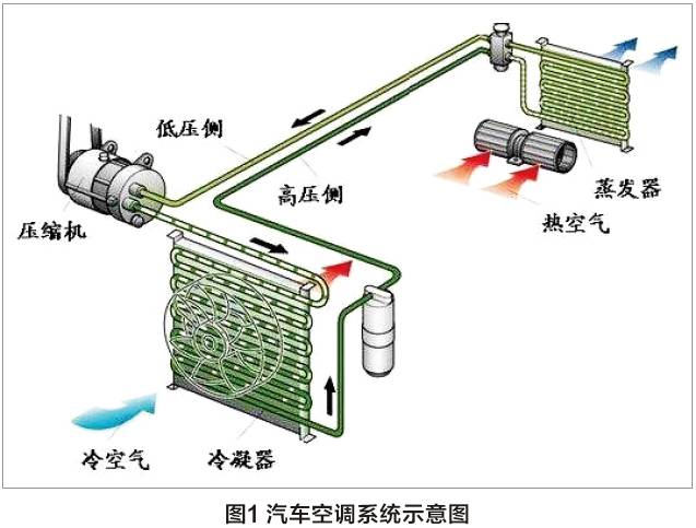
Automobile air-conditioning refrigeration systems consist mainly of compressors, condensers, liquid storage tanks, expansion valves, evaporationers, etc. The components are connected to the high-voltage pipe to form a closed system, which is equipped with a cooling medium, using the thermodynamic principle to be cooled through the air conditioning control system to achieve a comfortable indoor temperature of 20-22°c, air humidity of 45%-65%, as illustrated in figure 1。
Compression process: compressing low-temperature and low-pressure refrigeration gases into high-temperature and high-pressure gases from compressors。
Dispersion process: thermal decomposition of high-temperature, high-pressure gases into liquid by condensers。
Resilient process: higher temperature and pressure refrigerants are released into evaporation containers in the form of fog, with larger size and lower pressure and temperature after expansion。
Inhalation process: low boiling point refrigerants, heat evaporation in evaporation tanks, creating low temperature low pressure gases into compressors。
2. Automobile air-conditioning control system
Automobile air-conditioning control systems are largely two types of break-up and automatic control. Manual control, by definition, is the ability of the driver to achieve cooling heat by manual regulation. Self-activated ac is calculated by the ac control unit for the analysis of input signal data such as evaporation box temperature sensors, outdoor temperature sensors, sunlight exposure sensors, indoor temperature sensors, wind vent temperature sensors, pressure signals, etc. The ac control unit will perform the calculation through the execution of components such as electromagnetic ionizers, wind drums, wind vent electrics, etc., so as to preserve the purpose of the room temperature comfort。
Ii. Common ac malfunctions
Mechanical malfunctions: refrigerant insufficiency, compressor failure, expansion valve failure, system jamming, system leakage, etc., which can be judged by appearance inspection, pressure detection, use of leakage detectors。
2. Control system malfunctions, such as sensor failure, executioner failure, control unit impairments and circuit failure, which can be measured by diagnostic computers, universal meters and analysed in conjunction with circuit maps。
3. Other system reasons cause air conditioners not working, such as engine failure, transmission failure, etc。
4. Infrasound malfunctions: e. G. External belts, sharp rounding, pipe interferometry, internal animation compressors, expansion valves3 throttles, etc。
Iii. Maintenance of air-conditioning systems
1. Regular replacement of clean air conditioning filters to keep the air clean。
2. Regular cleaning of evaporation kits and wind-channel sterilisation。
3. Periodic replacement of the route system lubricant to ensure the useful life of compressors。
4. Add air-conditioning system protection agents to reduce the temperature of the wind vent and reduce engine loads。
Iv. Cases of failures
Fault phenomena
A volkswagen cc car, lfv3a23c8b3832479, which was purchased in august 2010, travelled 89 720km, had an air conditioner that was automatically cut off。
Disorder diagnosis
1. Using vas6150 to detect an 08-ac control unit, one fault code was found: refrigerant pressure exceeded the line. Based on the failure code, the ac control unit data stream was checked and the pressure in the 08-ac control unit was found to be 30. 6bar (1bar = 105 pa)。
2. Inspection of engine control unit 137 data streams:
Sector 1: ac switch signal displays a high level (means the ac is on)
Sector 2: display air conditioning compressors cut
Sector iii: display of 28bar pressure of the air conditioning system
Zone 4: show the percentage of dissipated fans。
3. On the basis of the above-mentioned tests, the dispersive fan was first checked and the fan was found to be turning and stopping。
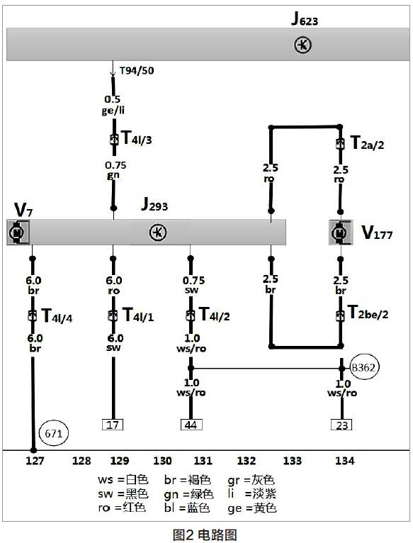
4. According to the circuit chart (figure 2), the fan power source was checked, which revealed that the fan plug-in t4x/4 foot was abnormal, that the circuit chart was consulted and that the fan was located at 671 points on the front left。
5. Inspection of the site 671 did not reveal a ground line; a careful examination of the vehicle revealed an accident in the front of the vehicle。
6. Raise the vehicle and check the lower side of the left beam and find traces of modified beams; the beam is removed and the beam is found to be a line 671。
7. Analysis based on the above test results: the vehicle's air conditioning system is under high pressure and non-refrigeration is due to poor heaters。
8. Air conditioning is normal after handling the ground line and testing the vehicle。
Causes of malfunction
Poor heaters caused the fans to work, caused heat dissipation, overstretched the air-conditioning system, led to a halt and the system coded。
Fault analysis
From an analysis of the failure code, it is possible that the reason the air conditioner is not working is that the system is under too much pressure, and it is possible to make a preliminary analysis that the air conditioner is not working because the pressure is too high. High pressure is caused by system over-relationship, electronic fan dissipation, or circuit problems. Analysis of data flow measurements shows that pressure is indeed high. Analysis of air conditioning controllers by principle should not be problematic, while measurements show that fans are close to 100% empty, which is not normal, and it can be concluded that the problem is in the fan controller here. By measuring the location of the power box, the negatives were poorly connected, causing the air to overpressure and causing the air conditioning to be cut off。
Fault management
Reprocess the wires to the iron point, trouble is off。
Recommendations for maintenance
Through the maintenance of the case, it is recommended that in future, when repairing car air conditioning, readers first acquire basic knowledge of the air conditioning principles of the vehicle and understand the performance of the various components of the air-conditioning system in order to analyse specific malfunctions. In case of failure analysis, a comprehensive judgement is made using self-diagnostic functions, performance functions and data streaming units in the computer, because now most of the computer modules are bus lines, data integration is more common and maintenance is time-consuming and unprecious in the original repair logic. It is also necessary to learn how to read and apply the circuit map, to find the route accurately, to connect each point and place, to draw up a map of the route for its own overhaul, to mark the results in the chart and to avoid double checking. Emphasis on power supply, ground-to-ground inspections must be carried out to measure the connection, the control unit loaded, and the results of unplugging or loadless tests are inaccurate! Finally, there's an analytical summary, a constant upgrading of technological capabilities and more efficient work. (the basic classification, composition and basic working principles of car air conditioning were presented in the basics lecture section in august 2016, for more information on the issue)