
Kj004 controlled silicon migrations triggered circuit
Kj004 controlled silicon mover triggered circuits are applied to single-phase, three-phase fully controlled bridge power units, which are activated by a two-way pulse transfer as controlled silicon. Kj004 units output a transient pulse of 180 degrees between two paths, which can easily form a fully controlled bridge trigger line. The circuit has a high output load capacity, a good migration, a good positive and negative half-week pulse phase balance, a wide shift range, low requirements for synchronized voltage, and functions and characteristics such as a pulsed output end。
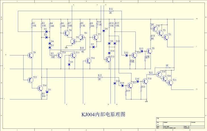
I. The principles of circuit work:
The circuit consists of the simultaneous detection of circuits, the formation of sawn-tooth waves into circuits, the deflection of voltage voltage, the combination of transfer voltages, the magnification of circuits and the power-phase magnification of circuits. The principle of the circuit is shown in the figure below: the slopes of the sawn waves determine the values of charged currents and points c1 from the external r6, rw1. Control v1 for different migration items only changes the ratio of r1, r2 and adjusts the corresponding deviation of the vp. At the same time, adjustment of the sawtooth slope rate rw1 allows different transfer controls to reach the full range. The trigger circuit is of a positive polar type, i. E. The transfer phase voltage increases and the guide angle increases. R7 and c2 form a differential circuit, changing the values of r7 and c2 and allowing different pulse output. The synchronous voltage of kj004 is any value。
Ii. Form of envelope:
The circuit is sealed in two columns directly in c-16 white and black tiles, the size of which is set by the ministry of electronic industry. Semiconductor integrated circuits outer dimensions sj 1100-76
Iii. Typical wiring and dot waveforms
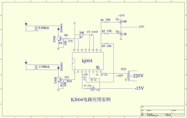
The synchronous chain of resistance r4 selection is calculated as follows:
R4 = (sync voltage 2-3) x 1000 times
The dots are as follows:
Electrical parameters:
Power voltage: straight current + 15v, 15v, allowed to fluctuate by 5% (+10% functional)。
Power current: positive current 15ma, negative power 10ma。
Synchronized voltage: any value。
Synchronization input allows maximum synchronized currents: 6ma (valid value)。
Move phase range 170° (synchronous voltage 30v, simultaneous input resistance 15k times)。
The sawn cortex range is 10v (the range is based on the sawn cortex level)。
Output pulse: (1) width: 400 ms ~2ms (achieved by changing the pulse width barrier element)。
(2) range: 13v。
(3) kj004 has a maximum output capacity of 100 ma (emission pulse current)。
(4) inverse pressure of the output tube: bvceo=18v (test condition ie≤100 μa)。
Positive-and-negative half-week pulse phase uneven by 3°。
Using ambient temperatures of four degrees: c:0~70°c r:~55~85°c
E: -40~85°c m:~55~125°c


