
In order for the circuit using the controlled silicon (scr) to function properly, the trigger circuit should provide the trigger signal at an accurate time to ensure that it is activated when required。
In general, the trigger circuit used to trigger a controlled silicon 2scr shall meet the following criteria:
Three basic types of flasks are usually used to trigger signals: direct signal pulses and communication signals。
The trigger requirement is usually provided in the form of direct current voltage and currents, and since pulse signals are usually used to trigger a controlled silicon scr, the duration of triggering pulses also needs to be considered。
The range is precisely equal to the trigger pulse required by dc, which must have a sufficiently long pulse width to ensure that a fence signal is provided during the entire period of controllable silicon scr。
The width of the polar pulse of the fence is likely to decrease with the increase in the signal range of the fence and the reduction in the opening time of the controlled silicon. For high sensory loads, pulse width must be long enough to ensure that the anode current rises to a value greater than the locked current of a controlled silicon scr。
The figure below shows a simple circuit that uses a direct signal from an external trigger。
Switch s closed to open a controlled silicon scr. The closed switch imposes a direct current on the controlled silicon scr fence, which is highly biased by the source pole (v ). Once the silicon scr is controlled, the switch can be opened to remove the polar signal of the fence。
The diode d limits the range of negative grid signals to 1v and the resistor r is used to limit the grid's current。
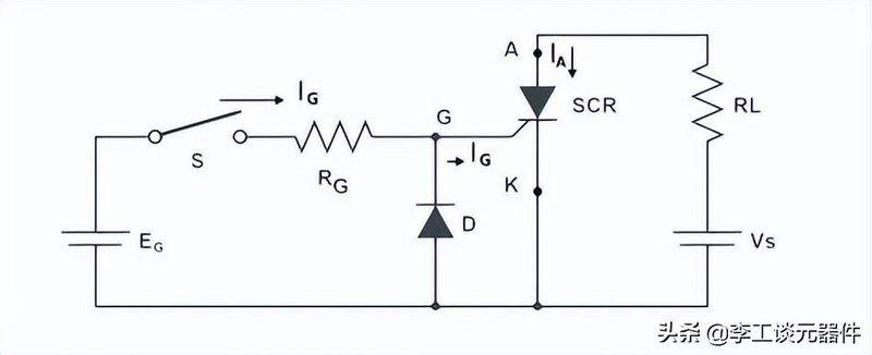
Simple, controlled silicon circuits
The figure below shows alternative circuits that provide grid signals from within the main power source, which operate in essentially the same manner。
It is not advisable to impose a constant straight-stream polar signal, as its power depletion will persist. In addition, in communication applications, the direct flow grid polar signal is not used to trigger a controlled silicon scr, as the presence of positive signals at the fence during the negative half-cycle increases the reverse anode current and may damage the controlled silicon。
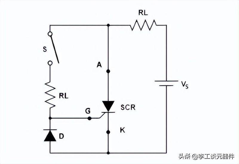
Alternative, controlled silicon circuits from inside the main power source
In order to reduce the dissipation of the grid's extreme power, the controlled silicon triggers a single pulse or a string of pulses, rather than a continuous straight-flow grid polar signal, which precisely controls the trigger point of the controlled silicon scr and, in addition, provides electrical separation between the controlled silicon scr and the trigger circuit。
If multiple controlled silicon scrs are selected from the same source, electrical isolation through pulse transformers or optical couplings is important and can reduce unwanted signals, such as transient noise signals, which may inadvertently trigger sensitive scrs。
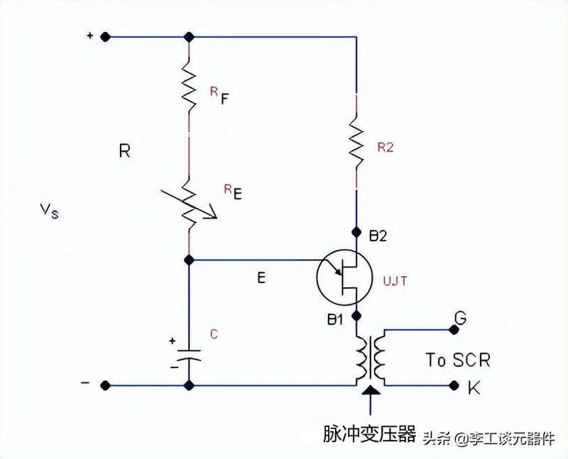
Controlled silicon triggers circuits -- pulsed signal circuits figure
The figure above shows the most common method of generating pulses using a single transistor (ujt) oscillator, which is well suited to trigger a controlled silicon scr。
It provides a series of narrow pulses at point b, and ujt is activated when the capacity is charged to the ut's peak voltage (v ). This will place a low electrical resistance on the ejective-base level 1 and launch the primary level of the extreme current over-pulse transformer, and will force the grid signal to a controlled silicon scr, which can increase the pulse width of the output signal by adding the value of c。
One of the difficulties with the circuit is that, owing to the narrow width of the pulse, it may not be possible to secure the locking of currents until the grid signals are removed. However, a rc buffer circuit could be used to eliminate the problem。
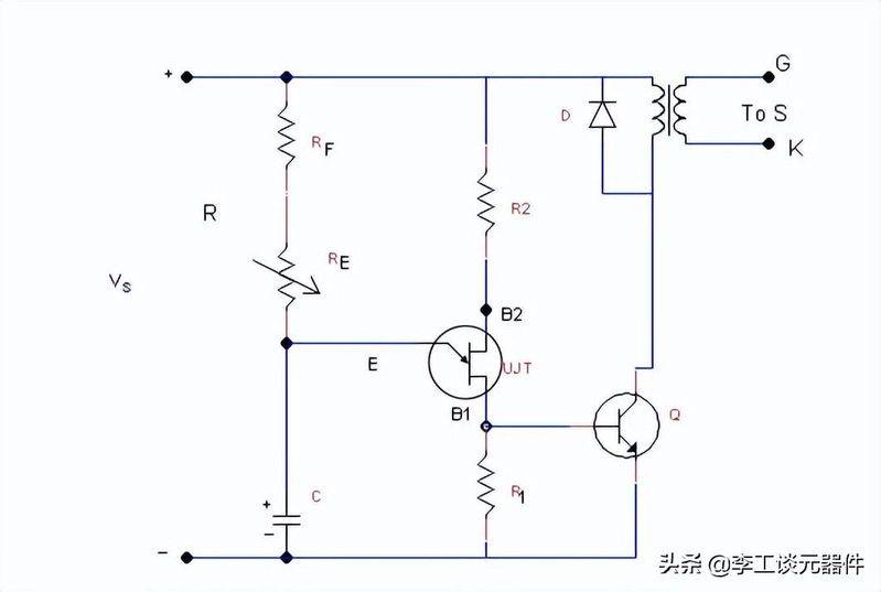
Controlled silicon triggers circuits -- pulsed signal circuits figure
Similar to the electrical circuits shown in the figure above, pulse width and increase time can be improved by using the r-side output to drive transistor q, which is linked to the transformer's primary string。
When pulses from ujt are applied to q's base pole, the transistor is saturated and the power voltage v is applied at both ends of the primary level, which will detect a voltage pulse in the pulse transformer's secondary sense, which is applied to a controlled silicon scr. When the pulse to the iq base pole is removed, it closes。
The current caused by the collapse of the magnetic field in the transformer senses a reverse polar voltage on the primary circuit, during which the diode d provides the path for the current。
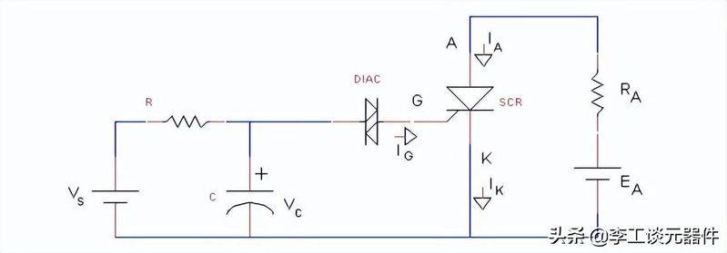
Diaac-like circuits
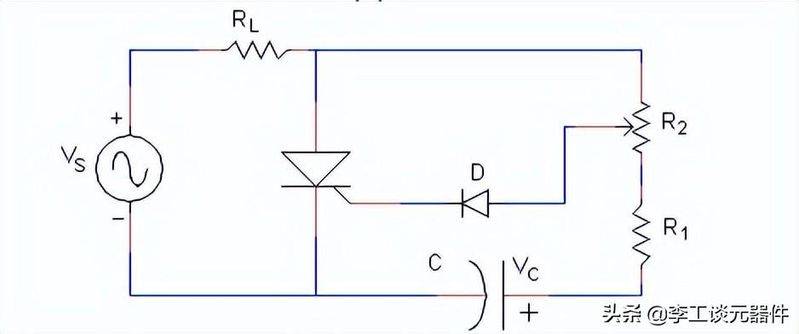
A similar circuit using diac (top graph) is slowly charged to the capacitor for a period of time determined by the rc time constant. When the capacity is charged to a charge equal to diac's plugged voltage, it will switch the diaac to a conductivity state。
The capacitor is then quickly discharged to the extreme of the fence of the controlled silicon scr, and after a short interval, diaac closes and repeats the cycle。
This arrangement requires relatively low power to charge the capacity from the direct current power source, but it will provide large power in a short period of time to enable a reliable and controlled silicon scr to be activated, as shown in the chart below。
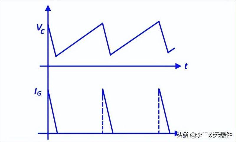
Wave chart
The following figure triggers the electrical separation between the control circuit and the load using optical coupling。
Catalysts can also prevent errors caused by noise or transients, which are particularly popular in solid-state relays。
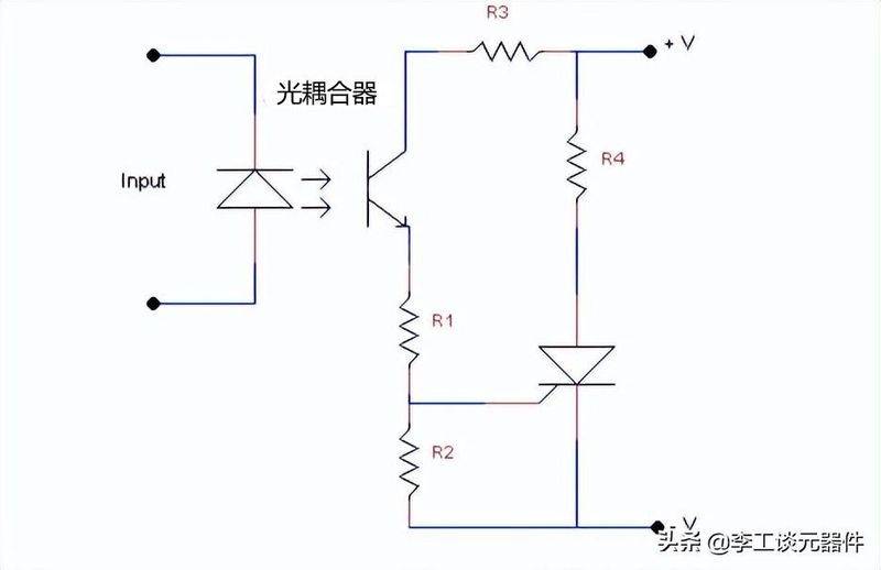
Optical coupling trigger circuits -- controlled silicon trigger circuits figure
The most common way to control a controlled silicon scr in communication applications is to obtain a trigger signal from the same exchange source and to control its application point for a controlled silicon scr during the first half of the cycle。
A simple resistance trigger circuit is shown below. Controlled silicon is in a positive blockage during a positive half-cycle. At a v value, the grid is high enough to open a controlled silicon scr。
Controlled silicon scrs are controlled by resistance r at the exact trigger, and diode d ensures that only positive currents are applied to the fence。
Controlled silicon triggers circuits -- communication signals
In the figure below, a rc circuit produces a door control signal。
The delay in voltage at both ends of c depends on (r+r) and (c), adding r would increase the amount of time required for voltage v to reach the level of sufficient grid current to open scr。
Controlled silicon triggers circuits -- communication signals
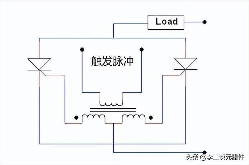
Controlled silicon scrs that are linked or connected shall be activated from the same source and at the same time, and this can be achieved by the use of relatively high grids to trigger voltage. The voltage can more quickly exhaust the controlled silicon scr, leading to consistent lead times. Pulse transformers are used to ensure that all fences are triggered simultaneously。
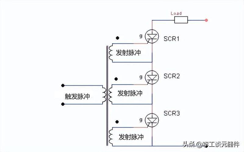
Controlled silicon triggered circuit - scr trigger
The graph below shows multiple sub-groups of fences with appropriate insulation to trigger pulse transformers. The transformer also provides electrical isolation so that the trigger source does not overload, thereby preventing other controlled silicon scrs in the group from being activated。
Multiple sub-circles with appropriate insulation trigger pulse transformers device
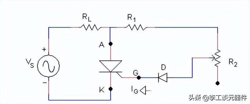
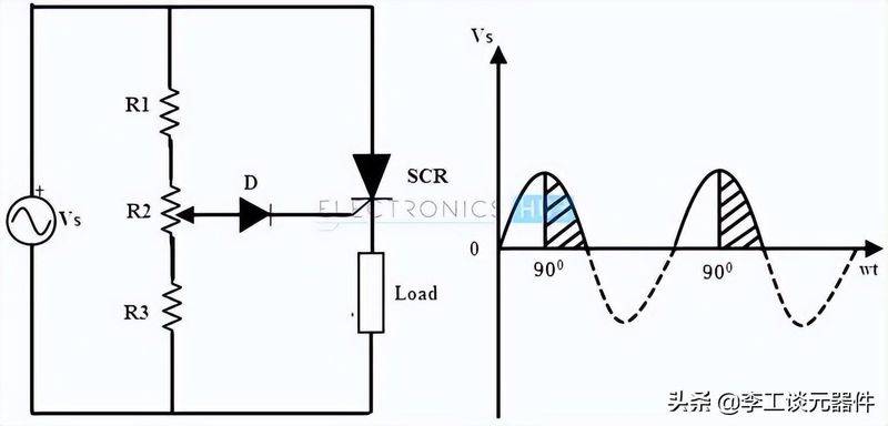
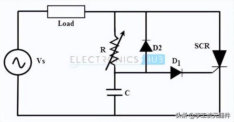
The circuit below shows a resistance trigger for a controlled silicon scr, which is used from input exchange power drive loads. Electrical resistance and diode combination circuits serve as grid-controlled circuits to switch scrs under the required conditions。
When the positive voltage is applied, the controlled silicon scr is biased and will not be transmitted until its grid current is greater than the minimum grid current of the controlled silicon scr。
When grid currents are applied by altering electrical resistance r2 so that grid currents should be greater than the minimum of grid currents, the controlled silicon scr is channeled, so the load currents begin to flow through the controlled silicon scr。
Controlled silicon scrs remain open until the anode current equals controlled silicon scrs maintain currents。
When the voltage is zero, the controlled silicon will be closed. Therefore, when a controlled silicon scr acts as a circuit switch, the load is zero。
The diodes protect the fence-driven circuits from the reverse fence's extreme voltage during the negative half-week of input. Retard r1 limits currents passing through the extremes of the fence, the value of which is that the currents of the fence should not exceed those of the maximum。
The resistance trigger circuit is the simplest and most economical type of trigger, but due to its shortcomings it is limited to a few applications。
In this case, the trigger angle is limited to 90 degrees. Since the voltage is maximum at 90 degrees, the grid current must reach the minimum grid current value between 0 and 90 degrees。
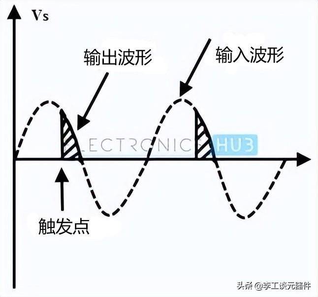
Rc trigger circuits can overcome resistance trigger circuits, which provide a trigger angle control of 0 to 180 degrees. By changing the phase and range of the currents of the grid, the use of the circuit can result in larger trigger-point changes。
The chart below shows the rc trigger circuit, which consists of two diodes, one of which is connected to the rc network to open the scr。
By changing variable resistance, the trigger or trigger angle is controlled throughout the full half-cycle of the input signal。
Controlled silicon triggers circuit -- resistance triggers circuit
During the negative half-week of the input signal, the capacitor is charged with the lower polar plane via the diode d2 to the maximum power voltage vmax. The voltage was kept at the --vmax end of the capacitors until the power voltage reached zero。
In the positive half of the input period, the controlled silicon scr becomes positive bias, and the capacitor begins to charge the trigger voltage value of the controlled silicon scr through variable electrical retardation。
When the chargeable voltage is equal to that of the fence triggers the voltage, the conductivity of the silicon is controlled and the capacitation maintains a small voltage. So, even after the input waveform passed 90 degrees, the holding voltage also helped trigger a controlled silicon scr。
In this case, the diode d1 prevents negative voltage between the fence and the cathode during the negative half-cycle of input via the diode d2。
Controlled silicon trigger circuit - resistor trigger wave chart
This is the most commonly used method to trigger scrs, since extended pulses at the extreme of the fence using r and rc trigger methods can lead to more power depletion at the extreme, and therefore the use of ujt (united transport) as triggers can limit power loss, as it produces a pulse。
Rc network connects to the launch extremes of ujt, which form the time circuit. The capacity is fixed and resistance is variable, so the charge rate of the capacity depends on variable resistance, which means controlling the rc time constant。
When voltage is applied, the capacitor begins to be charged through variable electrical resistance. The electrical resistance voltage has been altered by changing both ends of the capacitor. Once the electric capacity voltage equals the peak of ujt, it starts to conduct and thus produces a pulse output until both ends of the electrical capacity equals the grain voltage of ujt vv. The process repeats and generates a series of pulses at the base terminal 1。
The pulse output of the base extreme 1 is used to open the scr at the scheduled time interval。
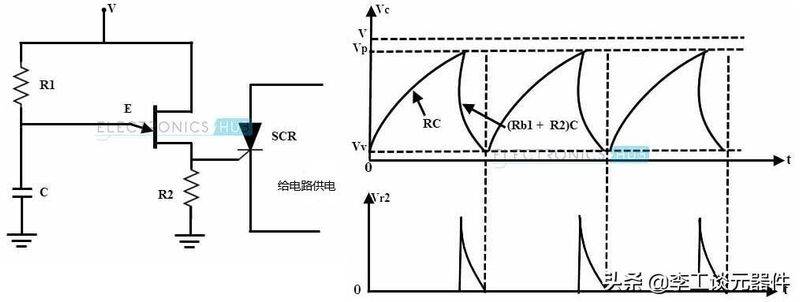
Controlled silicon trigger circuits - ujt ignition circuits


