I. Initiatives
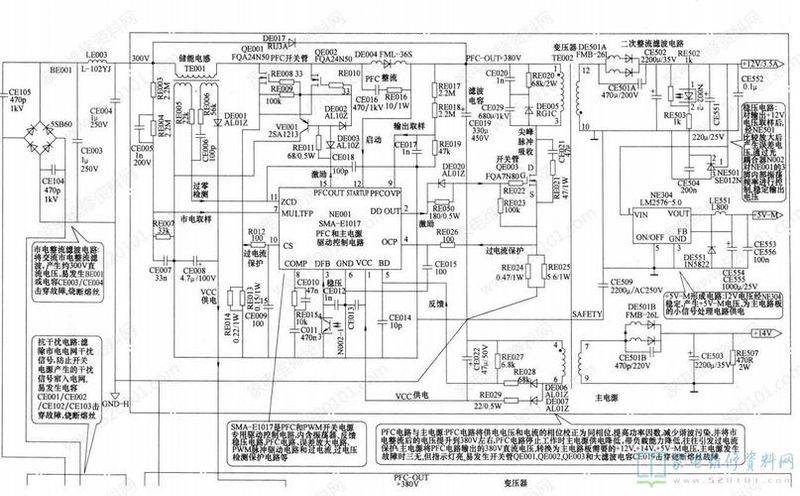
In the event of abnormality in the operation of the new section 850 dvd power circuits, the malfunctions were shown to be silent, remote control and inoperable. Whether or not the vfd screen is lighted through the front panel of the machine makes it possible to determine the approximate location of the malfunction。
If the power supply vfd screen is not bright and all key functions are not functioning without a sound map, the problem arises in the power source's one-off circuit and the cpu control system (mainly evrv 5v)。
The power supply vfd screens were activated, all key functions were disabled and no sound was shown to indicate that the switch power had been shaken and that the cpu control system had completed repositioning to normal, with problems occurring on the secondary power circuit。
The reasons for the failure of the switch on the power supply are many: first, the internal functionality of the thick membrane circuit q803 is well-functioning, but the external conditions required for self-inflicted vibrations are not adequate, and frequent stream-filtration wave circuits are short; the power-started electrical deformities fail; and the feedback circuit work is abnormal. The second is the failure of the internal function of the thick membrane circuit q803, which is commonly punctured by a switch。
The fuse f801 was burned, the thick membrane circuit q803 plastic-covered surfaces were flat and smooth, its 4-foot overflow detection of r808 surface coatings were coloured and its feet brightened, and the f801 melting cause was the current filtering circuit. One of the common bridge piping d802 - d805 reverse-shocked or leaked electricity, filtering cap c805 hit or leaked electricity; the surface of the thick membrane circuit q803 is convulsed, the surface varnish of the overflow detection resistance r808 is yellow and the lead welding point is oxidized, indicating that q803 has been damaged。
The filtering cap c805 positive voltage was measured at 300 v, excluding a one-time circuit. The q8034 foot voltage is monitored instantaneously, and if the watch pointer appears positive, it returns zero, indicating that the switch power is oscillated and, due to the load shortness of the circuit, the switch tube is protected by a mandatory power outage. A similar problem arises with regard to the q8024-3 foot light-sensitive triodec ~ e polar severe leak or penetration。
The table pointer remains non-jumping at zero, indicating that electricity is due to inadequate stress oscillation conditions, focusing on the initiation of resistance r804, d807, r805 in the feedback loop。
The damage to the internal switch in the thick membrane circuit was caused mainly by the loss or failure of the capacity of the filter cap c805 electrolytic fluid, which allowed the output +300v direct current voltage to carry a large amount of texture composition, and the equivalent effect in the switch cell pole, plus a relatively large positive feedback pulse. At the start of the shock, the two circuits of the switch tube at the extremes plus feedback voltage caused a sharp increase in the currents of the collectors, while the passover protection and the pulsation circuits had not responded to the motion, and the currents had been punctured by flash surges. In such a case, a single re-examination of the filter and thick membrane circuits is necessary。
The pass-over protection action is less sensitive and, in the event of a general overflow of the load, the protection circuit cannot respond to the lifting, causing the switch to operate at an overload temperature that is too high and is damaged by a deterioration of the durability. The new section's 850 dvd power source is identical to the dvd electrical circuit structure of the sd series, with the power voltage coverage being 110v-220v, and the utility overflow protection sample resistance r808 extraction value of 0. 62 times, which was designed on the basis of 110v/50hz (japanese grid-based). There is no doubt that this is the best option to work under 110 v voltage, and it provides high responsiveness to overflow protection circuits and allows reliable overflow protection of switches。
However, we use the 220v/50hz grid formula, which allows 100 per cent power efficiency if deterioration and loss are ignored, and the video discs work under 110 v voltage, with a turnkey charge of ic1 = w/v1 = 30/110 21/2a, with a switch charge of ic2 = w/v2 = 30/220 21/2a, and obviously with an ic1 = 2ic2. This equation indicates that when the exchange voltage changes from 110 v to 220 v, the working current of the switch tube is reduced to 1/2 of the original current as a result of the control adjustments of the electrical wiring circuit. If the overflow detection resistance r808 is constant, the action sensitivity to protect circuits is naturally reduced by a significant reduction in the electrical current of the switch. When the load appears to be in general short circuits, the electrical current of the main switch collection pole does not reach the original valve current and the circuits are protected by passing。
On the other hand, the one-fold increase in the voltage charge of the switch tube and the increase in the current charge of the condensed pole have resulted in a positive increase in the capacity of the switch tube. The choice of overflow detection of resistance in the visible power overflow protection circuit takes into account the icm, which is the upper limit parameter of the large power tube, and takes into account the other limit parameter of the high power tube under conditions of increased voltage during exchange of voltage. Otherwise, the switch was overloaded and damaged。
The solution is simple. R808 extractions are increased appropriately, depending on the user's location. If grid voltage is stable, r808 can choose between 1 and 1. 2 times。
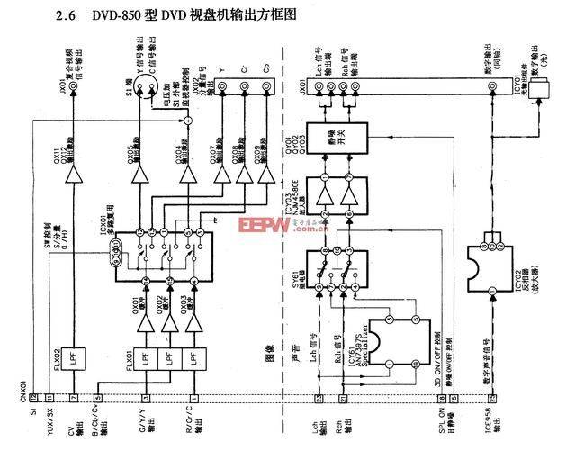
+9v, simulation +5v and number+ 5v is provided to the core server system (including rf magnification, server error signal formation, digital server and server drive, etc.), under the unified command of cpu ic601, processing the telecommunications signal detected by the 6 spectro-sensitivity receiver in the laser head into various control voltages, and completing the initialisation set-up of the vcr core by driving the magnification of the control wire and the electric press. The initialization process, like that of a normal computer, did not allow the first program set up by the software to be developed or adopted and would never enter the next program. In view of the inherent connection and coordination of the circuits, the three-way power supply is abnormal, and even if the cpu works properly, the wires and electric generators will not respond to any cpu operational instructions, so that the resulting failure is that the vfd screens are lit, but without drawings, all the keys are out of control。
These three circuits have two or more abnormal problems with the conversion of circuits by the o/off mode, with the numbers +5v, +9v and +8v short circuit protection and the +9v over-pressure protected circuits only being irregularly supplied, and the associated controlled circuits and the chain of steady voltage circuits checked. Overheating (tsd) protections are available within the power-pressure and protection module q821. When the internal temperature of the chip rises above 130°c, the tsd circuit is activated, cutting off the output of one foot, one foot, four feet, one foot, one foot, six feet, one foot, one foot, one foot, one foot, one foot, one foot, one foot, one foot, one foot, one foot, one foot, one foot, one foot, one foot, one foot, one foot, one foot, one foot, one foot, one foot, one foot, one foot, one foot, one foot, one foot, one foot, one foot, one foot, one foot, one foot, one foot, one foot, one foot, one foot, one foot, one foot, one foot, one foot, one foot, one foot, one foot, one foot, one foot, one foot, one foot, one foot, one foot, one foot, one foot, one foot, one foot, one foot, one foot, and nine feet, and nine feet. The output of the evrv (reserve) +5v power source from the 1 foot pressurer is provided to the cpu, which induces the vfd screen to remain lightless and silent, and all keys to fail. This situation can be confirmed by the temperature of the touch q821 chip, measured at 1, 4, 6 and 9 foot voltage。
Examples of troubleshooting
Example 1. Fault phenomenon: vfd screens are not bright, no pictures are silent and all key functions are not functional。
Analysis and overhaul: the inspection found that the fuse f801 melted and looked at the thick membranes q803 and 4 feet overflow to test the complete new light of resistance r808. Welded r808, replaced with a new safety tube and turned on f801 and burned again。
The screening of the filtering caps c805 and 4 of the contours d802-d805 revealed that d804 reverse resistance was only in the order of 10 euros. Following the d804 blast, direct currents passed through the closed circuits of d804 and d805, which quickly destroyed f801. In fact, the same result occurs when either arm of the bridge is pierced. Replacement of high-frequency fluids, troubleshooting。
Example 2: fault phenomenon: vfd screens are not bright, no pictures are silent, all buttons are disabled。
Analysis and overhaul: check the breakage of the safety tube f801, the rise of the surface switch on the thick membrane circuit q803 and the overflow detection of the varnished yellow on the surface of r808 and make a preliminary determination of the damage to the interior of the thick membrane circuit。
Welding r808 to replace the new safety tube, which is used to measure the positive voltage of c805 at approximately 300 v, indicates that the current filtering circuit is working normally. Q8033-4-foot switch c-e polar is measured as zero positive reverse resistance. Focus on the q8034 foot pass protection circuit。
A condition for the damage to the switch pipe due to the low sensitivity of traffic protection actions is that the load circuits are not working properly and that there is general overflow. Otherwise, even if the r808 circuit was short and the transient protection was removed, the normal load charge would not burn the switch. Check the secondary circuit load and find no excess trace. Switching to a thick membrane, a current gauge is normal in r808 and the only fracture is a slight shake of the needle. The second cause of damage to the switch pipe may be excluded from the normal current of the switch tube; the table pointer's shaking indicates a problem with the pulse-wide ring of the switch's current。
Regulates the input voltage and monitors the output of power +9v; monitors the q821{12} foot voltage and finds that {13} foot +9v voltage changes have not changed the end of the foot error amplifier, so that the truth is clear, the cause of the damage to the switch is the failure of the +9v error sample amplifier in the power pressure and protection module q8219{13} feet。
The error amplifier function is the error voltage. This refers to changes in +9v to the corresponding current changes; then changes in currents (through their internal luminous luminescular tubes) are converted by pvq802 to the corresponding electrical resistance (with an internal luminous tripolar c~e ~e endexion, which is used as a base bias barrier for the diversion control tube); and the diversion of the switches by ccd control, i. E., control of the conduct time of the switch by diverting, and stabilization of secondary direct flow voltage by adjusting the output pulse width。
The error amplifiers of the wide-wire circuits of the power supply have failed, and the five direct-flow output of the secondary circuit of the power supply has risen accordingly when the voltage of the grid has increased, while the corresponding five-way load has increased simultaneously, but the overflow detection of electrical resistance values has been small, the currents of the switch collection poles have not reached the trigger threshold, overloading the switch in the event of higher voltage and increased currents has been reduced to damage。
R808 was revised from 0. 62 to 1. 0, depending on the owner's reflection of the reality of the power supply at the location。
The power-pressure protection module la5611 market is not easily purchased, and its internal circuit structure shows that the foot error amplifier is completely independent, so that zigen can cut off the four lures and replace the failed circuit with separate pieces。
Example 3: fault phenomenon: vfd screens are not bright, no pictures are silent and all key functions are not functional。
Analysis and overhaul: check the integrity of the safety tube f801, measure the positive voltage of the filtered cap c805 at 300 v, monitor the q8034 foot of the thick membrane circuit to turn zero in the moment when the voltage is running, and clearly the failure substance is premature for power oscillation。
The r804 standard value for power start-up resistance is 510 k, and d807, z820 is good in the feedback circuit, and feedback is good in rounding 2-1 and storage is normal in rounding 6-3. Disconnector 3 foot electrical resistance r806, power oscillation work。
The light coupling device d802 was reviewed and severe power leaks were detected at the 3-4 footc-e polar level. Replacement of light coupling, troubleshooting。
Example 4: fault phenomenon: vfd screens are not bright, no map is silent and all buttons are not functional。
Analysis and overhaul: measurement of the q8033 foot voltage + 300v of the thick membrane circuit, with the instantaneous jump of the q8034 foot voltage remaining zero. In turn, the power source initiates resistance r804 and is receiving feedback that circuits z820, d807, r805 are in good condition, and q803 is being measured as having two to one feet of electrical resistance, replacing thick membrane circuits and malfunctioning。
Example 5. Fault phenomenon: vfd screens are not bright, no sound, all key functions are out of control。
Analytics and overhauls: the filtration cap c805 positive voltage is about 300 v, and the q8034 foot voltage is about 0. 12 v. It is clear that the switch power has entered oscillation and that a false load circuit consisting of r832, q826 in the secondary circuits has put in place safety protections under the 9v power supply, otherwise the switch collection pole current will not generate 0. 12 v at both ends of r808. Vfd screens could not be lighted to indicate that the central control system was not working properly。
Cpu enters normal working conditions: +5v working power, double pulse, system main clock. The absence of one of the three essential conditions resulted in the same failure of the first four power outages。
The measurement of the pressure protection module q8211 feet at zero and the additional test of the 5 foot + 6v voltage is normal, thus determining that the problem arises from the evrv + 5v pressurer at one foot。
Change module q821, troubleshooting。
Example 6? Fault phenomenon: vfd screen displays "00" with no sound, remote control and in-house key control。
Analysis and overhaul: vfd screens can be lighted to indicate that cpu enters normal work after re-entry. All operating keys are non-functional, and the problem arises in the o/offf-controlled circuits, protecting (exclusion of tsd) circuits or the three-way power supply of the server system (simulation of 5v, number 5v, +9v). What?
The voltage protection module q8212 foot voltage 6. 3v, in off mode. Recheck r828, d829, which indicates that the failure occurred at q827, entering circuits (including three-way power short-circuit protection)。
The q827-based polar voltage 0. 3v, the on method corresponds to the saturation conductivity of 0. 7v, and the relay plug-in cn8013 foot voltage (ic601 {6} the foot output oh level) of 2. 8v is normal, followed by r831 and d830 to detect the deterioration of r831. Replacement of electrical resistance, troubleshooting。
Example 7. Fault phenomenon: vfd screens are lit, no sound, all key functions are inactive。
Analysis and overhaul: measurement of q8212 foot voltage is 0. 7v, which precludes the possibility of q827 input output and protection of functional circuits, indicating that the problem has arisen in the three-way supply of electricity. Measuring q8214 foot simulation +5v output voltage normal, q823 emit polar voltage +5v, and q824 set electrode voltage +9v, from which the entire switch power system is intact。
The step-by-step check of the 4th, 5th and 7th feet of the cn801 plug-in found that the foot 5 + 9v plug-in was loose and that there were 2. 6k exposures. The plugs are welded directly using short-conductive lines and the test-starter failure is eliminated。
Example 8? Fault phenomenon: vfd screen displays "00" without sound and all keys fail。
Analysis and overhaul: measurement of q8212 foot voltage 0. 7v, additional measurements of q8214 foot, q823 launch pole and q824 set electrode voltage, resulting in q8214 foot voltage only 0. 2v, disconnection of the 4th foot simulation +5v power load of cn801 and failure to return. The q8215 foot voltage +6v was also measured, so the failure was judged to be simulated at q8214 foot by the +5v pressure stabilizer. Replacement of pressure control module, troubleshooting。
Example 9? Fault phenomenon: vfd screen displays "00" without sound, and all buttons do not work。
Analysis and overhaul: measurement of q8212 foot voltage 6. 3v, power stationing in off mode, problem at ic601 {6}/foot to off control circuit。
Disconnect r831 and measure cn8013 foot voltage 2. 8v, which indicates that cpu has issued an on directive. D831, d832 and d833 in d829, d830 and q827 are well separated in turn from d828 and d831 in d8v/+9v short-circuit protection and d833 in +5v short-circuit protection. As a result, d833, the power source entered the working methods of on, but the number +5v was not exported。
The +5v voltage of the power adjusting tube q823 is controlled by both the q8216 foot level and the q825-category. Disconnect q825 set electrodes, recovery of +5v output. Replacement of q825, troubleshooting。