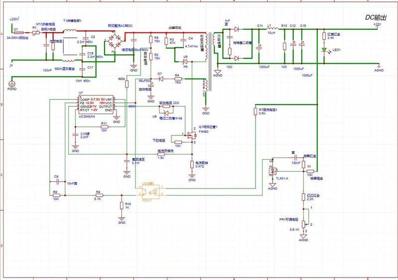
All right, let's elaborate on the typical switch power circuit and its working principles based on ud38422/uc3843/uc3844/uc3845, commonly known as the 3842 series, whose core works are very similar. This is the pwm chip, which currently uses a very extensive current mode。
Overview of core components
Master chip (ic): uc3842/3/4/5. It's responsible for generating pwm pulse signals, the core brain of the entire power source。
Main function leads:
Power switch (q1): it is usually the mosfet. Based on the pwm signal sent by ic, it quickly steers and shuts down the direct flow into the high-frequency communication spectrum。
Hf transformer (t1): core energy conversion element。
Output flow & filter circuit:
Feedback control loop: achieve output voltage stabilization。
Pressure baseline source & error amplifier (u2): common tl431 (modifiable baseline/ error amplifier)。
Enter & start circuit:
Current detection circuits:
Absorption return path (snubber): (possibly dsnub, rsnub, csnub)
Vcc own power circuit:
(step-by-step)
Start-up phase:
Work & power transfer (switch pipe conductor phase):
Work & power transfer (switch switch break):
Feedback control loop (pressure process):
Isolated transmission: increased led currents and increased lighting inside the led. Primary control: ice (from vref through restricted current resistance rfb) into ic fb (pin 2) increased. Pwm adjustment: fb attracts an increase in voltage. In the internal logic of uc3842, the fb's high boot voltage will lead to a reduction in the internal error amplifier output of the comp (comp and fb are the same changes, but a reduction in the comp voltage will lower the current comparator threshold). More critically, current mode control limits pulse width by testing isense (primary current peak). Result: vout rise = tl431 cathode current = led current = led current = led = led = led = led = led = led = eb voltage = cb voltage = cfp = php limit = tm = tm = quantification = quantification = led energy reduction = drop > vout. And vice versa。
Overflow protection:
Unpressed lock (uvlo):
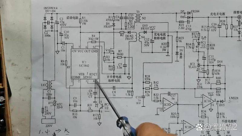
Key points summation of protection function: overflow protection through primary peak current detected by pin 3 (when vrsense > ~1v off); underpressure protection through uvlo. Commencement and power supply: high-voltage start-up, followed by transformer-aided circuits (self-electric). Key design: oscillation frequency (rt, ct), transformer design (swidth, e-sensor), current detection resistance (rsense), feedback loop compensation (r, c, c, compensation network between comp and fb - no typical compensation network is shown in the chart), absorbent circuits, ctr (flow transfer ratio), tl431 fraction voltage resistance ratio. Understand circuit charts
When viewing the circuit map, each element and its connection is identified according to the functional module described above. Particular attention is paid to:
3842 chips were found (mark u3842, ic1, etc.). Vcc power supply route (high pressure - > rstat - > vcc & auxiliary circuit - > current pipe - > vcc cap). Find power tube (mosfet) and its driver connection (ic pin 6 - > mosfet gate). Current detection of resistance (rsense links between mosfet sourse and gnd and links to ic pin 3 via filter network). Primary circuits of transformers were found (connecting to input high pressure and mosfet drain), secondary circuits (connecting flow pipe dout and output), and auxiliary circuits (connecting to supply auxiliary flow pipe dvcc). Can not delete folder: %s: no such folder remittance loop core component found: oscillation frequency setup component (rt, ct connected to ic pin 4). Absorption circuits (rcd or r+c or rc+diode combinations combined in primary circuits) are found. Debug note
Understands this standard structure based on uc 3842, you can read most of the common 3842 counter-heat power source drawings。