Uc3842 tabulations and functions
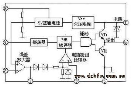
Uc3842 is a high-performance fixed-frequency current-type controller consisting of units such as error amplifiers, pwm comparators, pwm lockers, oscillators, internal baseline power sources and pressure locking, as shown in figure 1。
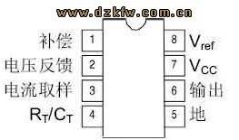
The functional description of the tubes is as follows:
One foot comp is the output end of the internal error amplifier, which is usually connected to the feedback network between the foot and the two feet to determine the gain and frequency of the error amplifier。
The 2 foot feed back is the feedback voltage input end, which compares the foot with the internal error amplifier with the baseline voltage (usually +2. 5v) to the input end, producing a controlled voltage to control the width of the pulse。
Three feet isense is an electrical sensor. In peripheral circuits, the source poles of power switches (e. G. Vmos tubes) are bundled with a small-value sample resistance to convert the currents of pulse transformers into voltage, which is delivered to three feet to control the pulse width. In addition, when power switches are increased when power voltage is abnormal, uc 3842 stops output when the power switches are more than 1v on the sample resistance, effectively protecting the power switches。
4 foot rt/ct is the time end. The public end of the time-capacitor c and the time-retardation r is attached to the saw-tooth wave oscillator。
Five foot gnd is the site。
Six feet of out is the output end. This foot is the totten column output, driven by ±la. This totem column structure is beneficial to the failure of the power pipe being driven because, when the tripolar vtl is closed, the vt2 conduit provides a low-obstructive reverse flow circuit for the power pipe and accelerates the power pipe break。
Seven foot vcc is power. Uc3824 does not work when the power supply is less than +16v, when it consumes less than 1 ma. The input voltage can be obtained from high pressure relief by a large resistance. After the chip works, the input voltage fluctuates between +10 and +30v, which is below +10v. The electricity consumed during working hours is about 15 ma, and the current can be provided through feedback resistance。
8-foot vref is the base voltage output, which can produce an accurate +5v baseline voltage with a current of up to 50 ma。
Uv3842 has a voltage adjustment rate of 0. 01 per cent, operating frequency of 500 khz, activated current of less than 1 ma, input voltage of 10-30 v, base voltage of 4. 9-5. 1 v, working temperature of 0-70°c and output of 1a。
Uc3842 typical application circuit (i)
The following is a typical application circuit of uc 3842 with transient pressure protection. Figure
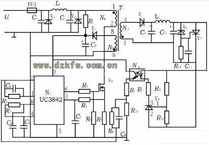
Figure uc 3842 application circuit chart
Overflow protection principles: when load currents exceed rated values or output short circuits, resulting in an increase in the v4 currents of the switch pipe, the voltage feedback on r7 to the 3 foot, and when the voltage on r7 is greater than 1 v, narrows the convulsive width, lowers the output voltage and reduces the working voltage of uc 3842. When it drops below the fixed voltage, the passover protection circuit works to protect the power tube. Once the short-circuit phenomenon had disappeared, the power supply automatically returned to normal work。
Overpressure protection: when, for some reason, the output voltage is over-exceeded, the pressure pipe v6 leads, which triggers the transistor v7, which shorts the end of the output, and shows that pressure protection occurs in the form of overflow protection。
Typical application circuit (ii) uc3842
Uc3842 using a fixed operating frequency pulse-width controllable mode, there are eight induced feet with the following functions: 1 foot is the output end of the error amplifier and the external barrier element is used to improve the gain and frequency characteristics of the error amplifier; 2 foot is the feedback voltage input end, which compares the foot volt with the error amplifier's 2. 5v baseline voltage at the opposite end, generating an error voltage, thus controlling the pulse width; 3 foot is the current detection input end, with a reduced pulse width exceeding 1 v allowing the power to operate intermittently; 4 foot is the fixed end, the internal oscillation frequency is determined by the external resistance time constant, f = 1. 8/(rtxct); 5 foot is the public end; 6 foot is the thrust output end, with an internal lifting capacity of ± 1a; 7 foot is the direct flow source power supply end, with a back-up and over-pressure function, with 15 m/(rtxct); 8 foot is the baseline volt output end, with 50 ma carrying capacity。
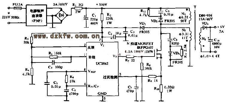
Uc3842 typical application circuit (iii)ac-dc circuit
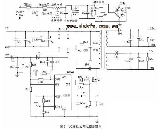
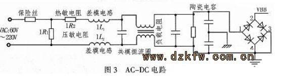
Ac-dc circuits transform communication into straight currents and are a prerequisite for the design of the back-heated switch power. Figure 2 shows the ac-dc circuit, where the input exchange voltage is 60 to 220 v and the resistance 1r2 is thermally sensitive resistance with a positive temperature coefficient to prevent overflow. 1r1 is used as a voltage-sensitive electrical barrier for wind surges. On pcb wiring requirements, a snake-shaped line is used between the pressure-sensitive electrical resistance and the zero line, and if the pressure-sensitive resistance is damaged, the pressure-sensitive resistance may be cut off in a timely manner before the circuit boards are burned because of the pressure-sensitive short circuit. Co-mode strangulation
The differential sense (1l1, 1l2) filters out the commodular and differential mode interferences, and the subsequent circuits are powered by direct currents from the whole of the bridge。
Typical application circuit (iv) uc3842
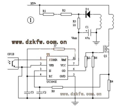
The protection of the 3842 circuits is typical of the circuits that are powered by uc 3842. Overload and short-circuit protection is generally achieved by sending current signals to foot 3 of 3842 by a chain of resistance (r4) at the source of the switch。
When the power is overloaded, the 3842 protective action reduces the ratio of space, lowers the output voltage, lowers the power voltage of 3842 vaux, closes the entire circuit when it is as low as 3842, and then starts the next start on r1, r2. This is called hiccup protection. In this state of protection, the power will work on only a few switch cycles and then go into a start-up process for a long time (in hundreds of ms to several s), with low average power and no damage to the power even if short circuits are exported over a long period of time。
For reasons such as leakage, some switches have a large switch peak in each switch cycle, and even when they are empty hours, the auxiliary voltage vaux cannot be reduced to a sufficiently low level, so generally a chain of resistors (r3) is attached to the adjunct to the whole current diode of the auxiliary power, which forms the rc filter and c1 filters away from the peak of the opening moment. A careful adjustment of this resistance value would generally achieve satisfactory protection. Using this circuit, care must be taken to select the lower auxiliary voltage vaux, which is usually 13-15 v for 3842, making it easier to protect。
Uc3842 summary of information in chinese (uc3842 quotations and functions working principles and typical application circuits)
Figure 1 is the most widely used circuit, yet it still has several problems protecting it:
1. At the time of bulk production, there will always be a number of power sources that are not well protected due to differences in metaware, which will require individual adjustments of the r3 values, causing production problems;
When the output voltage is low, e. G. 3. 3v, 5v, which, due to high output currents, does not decline significantly at overload, and it is difficult to adjust r3 to an ideal value;
3. While the auxiliary voltage vaux also follows output changes in positive applications, it is more relevant to input the voltage hv and it is difficult to adjust r3 to an ideal value. This would have been better if the protection break had been achieved by the use of auxiliary circuits. Accomplishment principle for auxiliary circuit shutdowns: lower output voltage during overloading or short circuits, no more guidance for the optic circuits for the feedback of the voltage, and delayed movement for a period of time when the optic circuits were detected no longer being directed。