Chapter 9 design and calculation of hydraulic systems

Loading...
Hydraulic systems are designed as part of the whole machine design and, in addition to meeting the requirements of the mainframe motion cycle and static, dynamic performance and so forth, should meet the conditions of simple structure, safe work safety, efficiency, economy and ease of use. The design of hydraulic systems varies according to the size of the system, the amount of information to be drawn upon and the experience of the designer. The design of the components is sometimes carried out interchangeably or even repeatedly。
The following steps are designed for hydraulic systems:。
1 clear design requirements and performance analysis。
2 main parameters of an initial hydraulic system。
3 development of a hydraulic system rationale。
4 calculates and selects hydraulic components。
5 validation of hydraulic system performance。
6 mapping of work and preparation of technical papers。
9. 1 clear design requirements, performance analysis 9. 1. 1 clear design requirements and working environment
When designing hydraulic systems, the following issues should first be identified and used as the basis for their design。
1 the use of the mainframe, the process, the overall layout and the requirements for the location and spatial dimensions of hydraulic thrusters。
2 host performance requirements for hydraulic systems, such as mode of movement, itinerary, speed range, load conditions, motor smoothness, accuracy, work cycle and action cycle, synchronization or locking。
3 working environment of hydraulic systems, such as temperature, humidity, vibration shock and presence of corrosive and flammable substances。
9. 1. 2 analysis of the situation
On the basis of clear design requirements, the mainframe should be subjected to a condition analysis, which should include motor and power analysis。
(1) sports analysis
The movement of the mainframe execution element as required by the process may be analysed by means of a shift cycle map (l-t) and a velocity cycle map (v-t)。
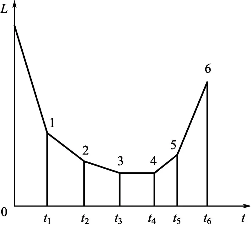
1 the shift cycle chart (l-t) is shown in figure 9-1 for hydraulic pressure presses. The figure clearly shows that the working cycle of the hydraulic presses consists of six stages, respectively, of fast down, slow down, suppression, preservation, slow-down of discharge and rapid return。
Loading...
Figure 9-1 hydraulic transition cycle of hydraulic presses figure
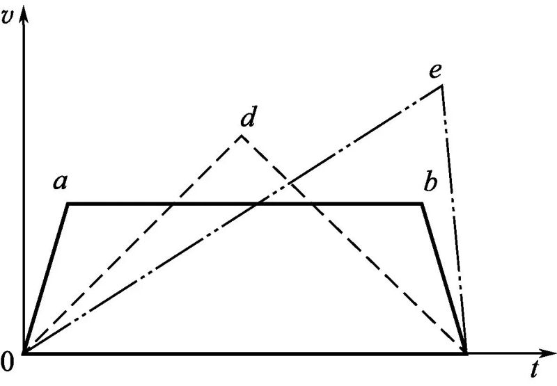
The motion characteristics of hydraulic cylinders in the project can be summarized as three types. As shown in figure 9-2, the velocity cycling of the three types of hydraulic cylinders, the first of which is shown on a solid line, begins to move evenly, then moves flatly, and finally slows down to the end; the second is shown on a dotted line, the first half of the total itinerary is evenly accelerated, the second half of the journey is motioned flatly, and the other half is motioned flatly and the acceleration is equal; and the third is shown by a dotline, where more than one and a half of the total journey moves flatly at a smaller acceleration, and then slows down to the end of the journey. The three velocity curves of the v-t chart not only clearly indicate the pattern of the three types of hydraulic cylinders but also indirectly indicate the dynamic properties of the three conditions。
Loading...
Figure 9-2 speed cycle of three types of hydraulic cylinders figure
(2) dynamic analysis
Power analysis is the study of the vulnerability of the machine to its implementing agencies in the course of its work. For hydraulic systems, the load of hydraulic cylinders or hydraulic motors is studied. In the case of hydraulic cylinders, the load is made up of six parts, i. E. Work load, direction friction load, inertial load, weight load, seal load and back load. These are briefly described below。
1 the work load fw different machines have different work loads, which are the weight of lifting weights for lifting equipment; for hydraulic presses, the axle deformation of suppressed parts is the work load. The working load is positive and negative when the direction of the hydraulic tank is opposite. The task load can be either a fixed value or a variable, the size and nature of which are analysed on a case-by-case basis。
2 track friction loads ff track friction loads are those for which the value is related to the mode of guidance, placement and state of movement of the motor component while the hydraulic tank drives the motion parts. The friction load calculation formula for the various forms of the track can be found in the relevant manuals. For example, guidance tracks and v-shaped tracks are commonly used on the machine bed, and when they are horizontally placed, the rail friction load calculation formula follows。
Altitude
Loading... (9-1)
V track
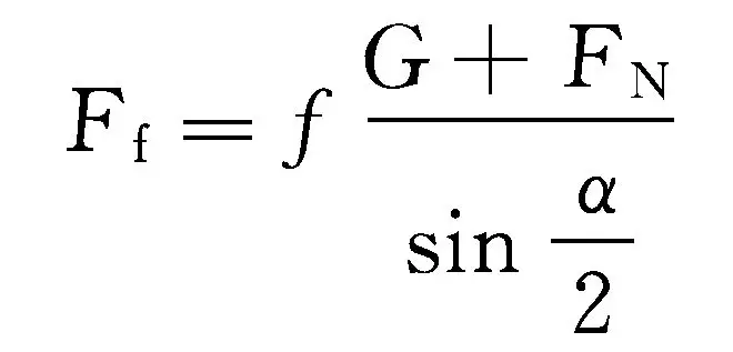
Loading... (9-2)
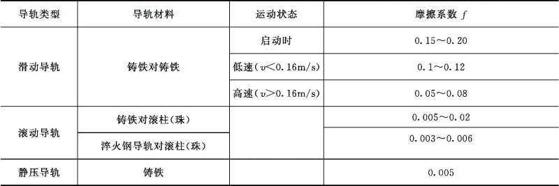
In formula, g is the gravity of the motion component; fn is the working load of the vertical track; α is the angle of the v track, normal α = 90°; f is the friction coefficient, the value of which can be referenced in table 9-1。
Table 9-1 track friction factorf
Loading...
3 inertial load fa inertial load is the inertial force of the motion component at the start acceleration or brake deceleration, the value of which can be obtained by newton's second law, i. E
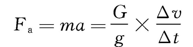
Loading... (9-3)
In formula, g for gravity acceleration; Δt for start-up, brake- or velocity conversion time; Δv for Δt-time velocity variation
4 the self-weight of a motor component with a gravity load of fg vertically or tiltly, which is also a load, and when tilted, only the weight of gravity in the direction of movement is calculated. Gravity is positive when the hydraulic tank moves, and reverse is negative。
5 sealed fs sealed load means the friction force of the hydraulic tank sealing unit, the value of which is related to the type, size, manufacturing quality of the hydraulic tank and working pressure of the fluid. Until the hydraulic system design was completed, the parameters of the sealing system were not known and their values could not be calculated. They were generally taken into account by the mechanical efficiency of the hydraulic tank, which was used with a mechanical efficiency of 0. 90 to 0. 97。
6 the back-pressure fb back-pressure load is the resistance of the hydraulic tank to the oil cavity pressure. It is not possible to calculate the system's programme and hydraulic tank structure until such time as it has been determined, and this may be waived in the load calculation。
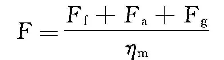
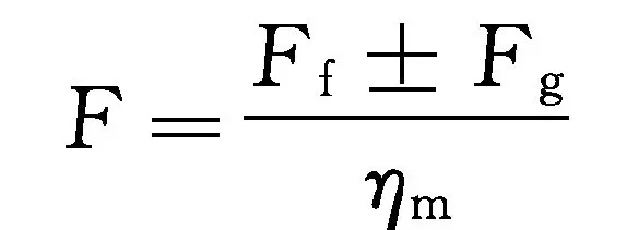
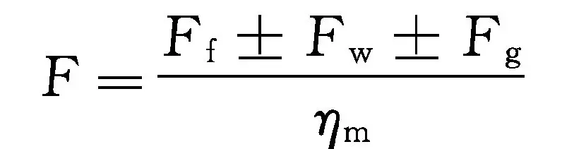
Mechanical load f for the main working stages of the hydraulic tank can be calculated according to the following formula。
Airborne launch acceleration phase
Loading... (9-4)
Fast-track phase
Loading... (9-5)
Progress stage
Loading... (9-6)
Brake deceleration
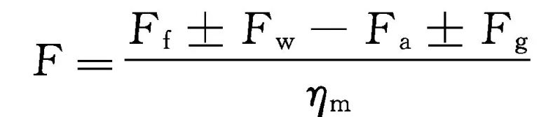
Loading... (9-7)
For simple hydraulic systems, the above calculation can be simplified. For example, single-quantitative pumps are used to provide fuel only to calculate the total load at the stage of work progress, and if a simple system uses a limited-pressure variable pump or a double pump for fuel, only to calculate the total load at the stage of speed and progress。
If the implementing agency is a hydraulic motor, its load-trading method is similar to that of a hydraulic tank。
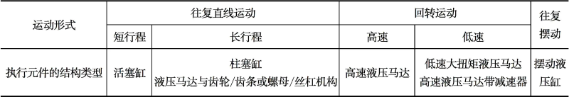
9. 2 calculation and selection of hydraulic components 9. 2. 1 structure type and parameter determination of the executing element
The type of implementing element structure to be used in the hydraulic propulsion system should depend on the type and nature of movement to be achieved by the host, as shown in table 9-2。
Table 9-2 selection of execution element structure type
Loading...
The structural parameters of the execution element are determined by working pressure and maximum flow。
(1) work pressure on primary execution elements
Work pressure is the main basis for determining the parameters of the structure of the performance element. Its size affects the size and cost of the execution element, and even the performance of the system as a whole, the work pressure is high, the execution element and the system structure is tight, but the strength, intensity and seal of the component is high, and the hydraulic pump of the higher pressure is required; conversely, if the work pressure is low, the size of the execution element and the system as a whole is increased and the structure is large, so that the work pressure of the execution element is selected according to the circumstances, and the work pressure of the execution element is based on the total load values, as shown in table 9-3。
Table 9-3 work pressure for selection of execution elements by load
Loading...
(2) identification of the main structural parameters of the execution element
The main structural dimensions to be determined are the diameter of the inner diameter d and the piston d of the tank, which is still used as an example, and the general methodology for calculating and determining d and d is described in chapter 4。
For systems with low-speed motion requirements, the effective work area of the hydraulic cylinder has yet to be validated, i. E., it should be guaranteed that
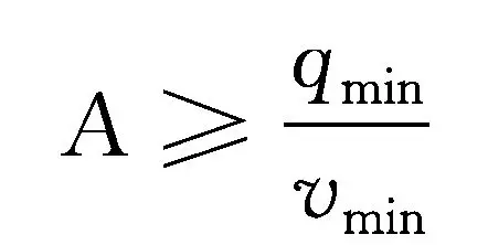
Loading... (9-8)
In formula a is the effective working area for the hydraulic cavity; qmin is the minimum steady flow of the flow valve to control the speed of the performance element, which can be detected from samples of hydraulic valve products; and vmin is the minimum working speed required for the hydraulic cavity。
If the results cannot be satisfied (9-8), it is stated that the design must be modified to the minimum speed required by the design size and programme。
(3) calculate the working pressure of the execution element
When the main sizes d and d of the hydraulic cylinders are calculated, there is generally a deviation between the standard and the calculated values of the cycle, and therefore there is a need for a work pressure test based on the round. In addition, the back pressure of the back road was not calculated during the determination of the work pressure according to the above method, and therefore the work pressure identified was only the pressure of the performance element to overcome the part of the pressure required to overcome the total mechanical load, which, after the determination of the structural parameter d, d, could be obtained by taking an appropriate back pressure estimate。
For a single rod, the working pressure p may be calculated using the following formula。
No cavity into the oil industry
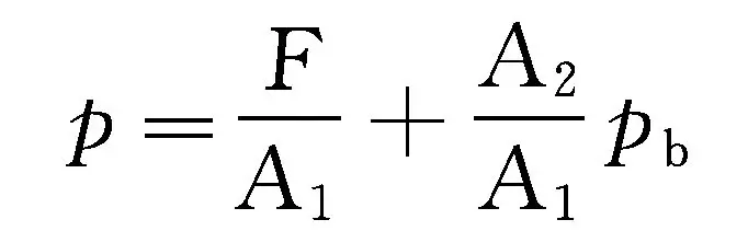
Loading... (9-9)
There's a cavity in the oil phase
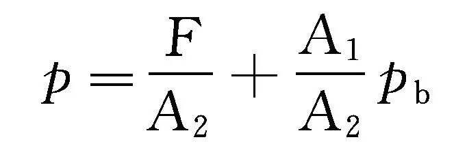
Loading... (9-10)
In formula f is the maximum mechanical load of the hydraulic cylinders at all stages of the operation; a1 and a2 respectively (b) the effective area with no cavity and cavity; pb is the back pressure of the hydraulic tank backway, which is recommended according to the design manual before the system design is completed。
(4) workchart for executing component
After the main parameters of each execution element have been determined, it is possible to calculate not only the working pressure of the execution element during the various stages of the work cycle, but also the flow and power required to enter, so that a working chart of the performance elements in the system in the course of their work can be made, i. E., a curve of changes in the pressure, flow, power to time or position of the execution element in a work cycle. Combine the work maps of the various implementation elements in the system and get the whole system. The working chart of the hydraulic system provides a reasonable basis for the selection of components, the choice of circuits or the modification of the design in subsequent design steps by showing the maximum values of system pressure, flow and power throughout the work cycle and their distribution。