Solidworks mechanical design: reversing the method of drawing the parts。
1. Hello, everyone. Welcome to the non-standard design class of the labour control corporation. Today we teach you how to draw such a reversal. Let's teach。
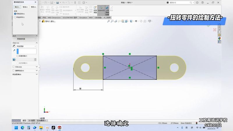
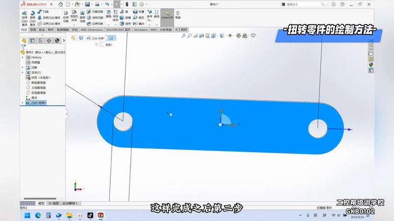
2. First step, the creation of a new part. When a new part is created, you choose to use a toolbar or a slot that will mark a dimension and give it a size of 30 and a length. After completion, draw two circles between them, which are equal in size, give it a 15, stretch the cavity, give it a 3 mm thickness, choose to make sure。
3. Step 2, choose to place and then select this side to draw a graphic, is it a square rectangle? This rectangle holds down the shift key, and this time gives it a support, selects stretch cut, and keeps all views。
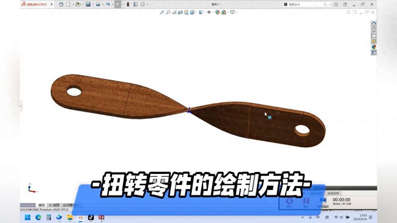
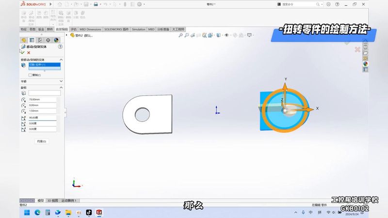
4. After this step, the direct editing command is enabled, the moving copy command is selected in the direct editing instruction and the moving copy command is selected in the direct editing instruction, see? To choose not to even, to rotate, to move the rotation time, this is the actual one, and then to make sure. It rotates along the x-axis, giving it a 90-degree rotation, and that's where the two parts are。
5. This is followed by the use of the sample machine cam inside the feature, which is then sampled on this side and this side, so that it can be moved upon completion, where it is not produced or produced. So it's just the reverse direction, and then it's bound up, for example, in terms of each other, and the next one in terms of each other。
6. The next step, for example, would be to limit them to one level and the next to one level, each with the first value and the choice。
7. The selection of the top colour after determination has been completed and such a graphic is completed. Did you learn