A8-2. 8l circuit chart 2003-2010
A8-3. 2l circuit chart 2003-2010
A8-4. 2l circuit chart 2003-2010
A8-6. 0l circuit chart 2003-2010
A8l-3. 0t circuit chart 2011-2014
A8l-4. 0t circuit chart 2011-2014
A8l-6. 3l circuit chart 2011-2014
A8l-3. 0tdi circuit chart 2014-2017
A8l-3. 0t circuit chart 2014-2017
A8l-4. 0t circuit chart 2014-2017
A8l-6. 3l circuit chart 2014-2017
A8l mixed circuit chart 2014-2017
A8l-3. 0t circuit chart 2018-2021
A8l-4. 0t circuit chart 2018-2021
A8l-3. 0t circuit chart 2022-2023
A84. 0 maintenance manual 2015-2021
A83. 0 maintenance manual 2015-2021
A83. 0 tdi maintenance manual 2016-2021
A84. 0 maintenance manual 2016-2021
A82. Maintenance manual 2016-2021
01
A8


Case name: audi a8l 3. 0t engine start-up difficult maintenance case
Car configuration: 2016 audi a8l 3. 0t, equipped with 3. 0 litres of turbine boost engine。
Fragmentation: the owner of the vehicle reflects the difficulty of ignition of the engine at the time of the cold start, even after the start has been successful, the engine has been unstable and has a visible shaking。
Maintenance:
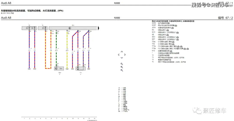
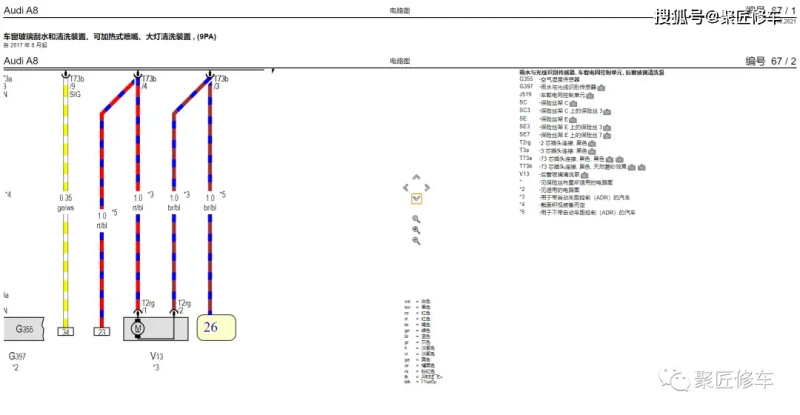
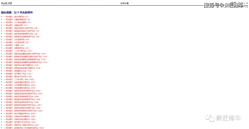
Fault diagnosis: using the a8l-3. 0t circuit chart, 2014-2017, the connector reads the vehicle failure code and found that the engine control unit (ecu) reported “arcular position sensor signal anomaly”. Sensor inspection: according to the a8l-3. 0tdi maintenance manual 2016-2021, the cortex position sensor is checked to confirm whether the sensor is damaged or needs cleaning. (b) sensor replacement or cleaning: if the sensor is damaged, the new arc location sensor is replaced in accordance with the guidelines of the maintenance manual; if the sensor needs cleaning, the corresponding cleaning is performed. Circuit inspection: check the circuit connection of the curved axis position sensor to ensure that there are no broken or short circuits, with reference to the a8l-3. 0t chart, 2014-2017. Engine control unit inspection: check the software version of the engine control unit and update it as necessary to ensure compatibility with sensors and system stability. System testing: after replacing or cleaning the sensors, clear the failure code and conduct system tests of the engine control unit to ensure that the curved position sensors are normal. Engine testing: start the engine, check if the operation is smooth and confirm that the dithering phenomenon is gone. Road test certificate: a road test with the owner of the vehicle was conducted to confirm that the engine was functioning normally and that there were no anomalies in the vehicle's operation。
Summary of cases:
Engine start-up difficulties and operational instability may be caused by the failure of the corrosive position sensor. The maintenance will require a combination of maintenance manuals and circuit charts to perform a full inspection and maintenance of the engine's curved position sensors. The replacement or cleaning of sensors and the upgrading of the engine control module software are important steps in addressing engine failure. System tests and road test certificates are important elements in confirming the effectiveness of maintenance and need to ensure the safety of vehicle performance and movement。