
The liquid switching valves are the transformer valves that use pressure oil to control the oil routes to change the position of the core of the valves, and the structure and functional symbols of the three four-line liquid switching valves are shown in figure 5-9。
The core of the valve is moved by the pressure margin of the fluid in its sealed cavity at both ends. When the pressure oil that controls the oil route enters the right of the slide valve from the control mouth k2, k1 moves back to the right of the valve, the core moves back to the left, connecting the pressure vent p to b, a to t; when k1 connects the pressure oil, k2 moves back to the right, making p to a, b to t; and when both k1 and k2 go back to the oil, the valve core returns to its middle position under the spring and positioning trap。
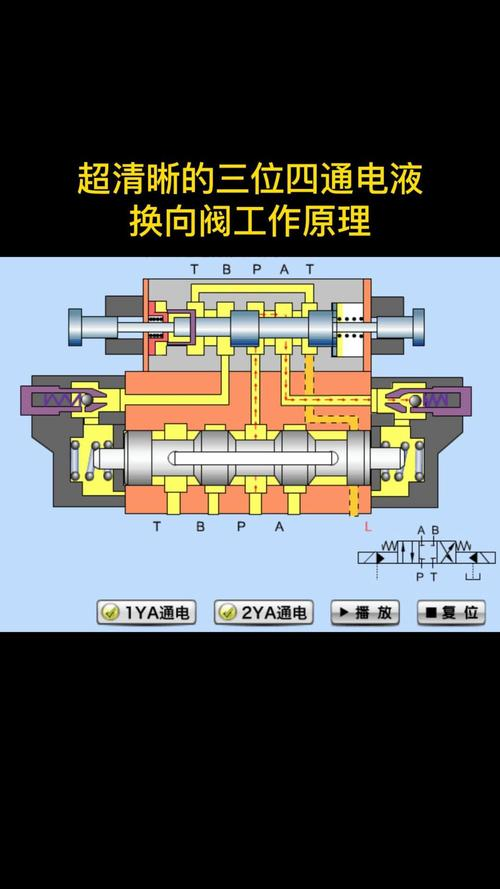
Figure 5-9 three four-wire liquid transformer valves (a) structural chart (b) functional symbol chart 5。
In large- and medium-sized hydraulic equipment, when the flow of the valve is greater, the friction and fluid power on the slide valve is greater, when the electromagnetic thrust of the electromagnetic conversion to the valve is relatively small and there is a need to replace the electromagnetic conversion valve with the electron exchange valve。
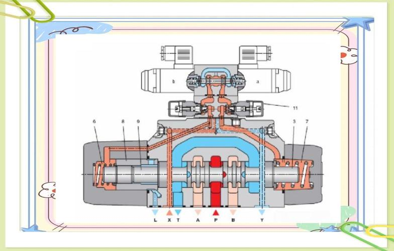
The electron conversion valve is made up of a combination of an electromagnetic slide valve and a hydraulic slide valve。
The electromagnetic slide valve is a precursor that can change the direction of the control flow and thus the location of the liquid slide valve core。
Since the hydraulic thrust of the hydraulic slide valve can be large, the size of the main core can be very large, allowing for larger flow of fluid。
That way, smaller electromagnets control larger fluid flows。
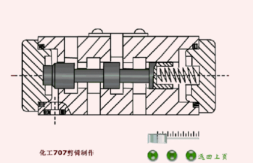
(c) simplified functional symbol 1,6-scaling valve 2,7-directive valve 3,5-electromagnetic-4-electromagnetic valve core 8-main valve core? The structure and functional symbol of the main valve, shown in figure 5-10, is that the control fluid in the main valve core at the right end of the spring can be moved to the right after the electric magnet on the left of the electromagnetic valve and move its core to the right, and control pressure oil from the main valve at the p-port or the external intake can be reducted to the left by a mobile throper on the left, leading to the movement of the main valve core to the right, the control fluid in the main valve core at the right end of the valve through the right-flow valve through the b-l and t-l and then by the t-barreling to the right; when controlled pressure oil from the main valve p or the external throttle is removed from the left and right cavity of the main valve core, the fluids of the main valve core and the two cavities of the main valve flow back to the tank via the middle of the lead electromagnetic valve in a, b, and the lead electromagnetic valve t, as shown in figure 5-10b。


