Fault phenomena
A benz e200, code 212. 134, manufactured in 2014, equipped with a 274920 engine, 722. 9 velocity automatic transformer, with a mileage of 55,633 km。
The vehicle has been in regular use and has been routinely maintained, and during a birth report, during a check-in of the police, the maintenance staff found that the vehicle needed longer ignition to start, and that engine failure lights on the dashboard were frequent. The owner didn't know what it meant to call the alarm on the counter, so he didn't care about it, just thought it was different when the engine started。
Diagnosis and elimination of malfunctions
After the pick-up, the owner was asked some questions about the normal use of the vehicle. It's known that the car has been fixed to refuel at the gas station, that there have been no power problems before, and that the engine is no different than before. It's just that there's an engine failure alarm on the dashboard and it's not clear when it's going to take longer to start。
As a result of the failure lights on the dashboard, the vehicles were first quickly tested with a dedicated computer and two fault codes were found in the engine electronics med40 (me engine electronics) of n3/10 - internal combustion engine m274:
P001685 the position of the input cam axis (cylinder 1) is not credible compared to the position of the curve axis, with a signal above the permitted limit; the state is s, has been stored down and has caused the engine to activate the failure light。
P119012 - the "injection pressure" sensor has a very short path and is stored。
As a result of storage failure, and in order to verify the failure, a decoded road test vehicle was performed. Each start-up engine takes about 5s, which is higher than the normal start time. The engine failure alarm is activated after start-up. There's no apparent anomaly in driving to test vehicle power. When we got back to the factory, we reread the fail code, and we found only one "p001685"。
The factors affecting the time required for engine start-up are generally fuel pressure, engine mechanical components (time, tank voltage), engine electrical controls (sensors, computer controls). Because the same malfunction code p001685 appears every time a vehicle is restarted after a failure code has been removed, locks the failure point on the engine and directs the failure code to lead the outcome to check the engine (figure 1)。
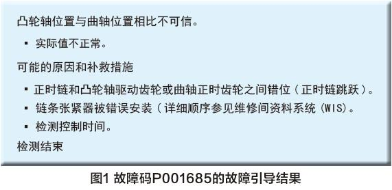
Checking the time system according to the method shown in figure 2 shows that the actual position of the input cam axis has shifted, so it is generally possible to judge that the failure of the vehicle is due to the timing of the flow of the cam axis。
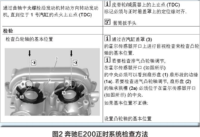
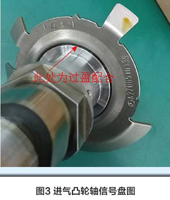
For further repair, the gas chamber covers were removed for correct-time proofing, after which it was discovered that there had also been a shift in the signal discs of the inbound cam axis, and it was found that the input cam axes were over-compared with the signal disc (figure 3) and had to be replaced with the re-corrected-time。
In order to ensure a one-time recovery rate, the fuel pressure and the cam axis sensor lines were tested, and when the engine was not working, the oil track pressure was 35bar (1bar = 105pa) and the low pressure fuel pressure was 4. 5 bar; and the ingestion cam axis sensor plugs were 5v, 0 and 0, respectively. The line between the sensor and the engine computer has a road barrier value of 0. 8 times and a train-to-ground electrical resistance of 0. 8 times; the test results are normal. So, it's quite possible to lock down the failure point at the input cam axis and shift it to the signal disc。
When the cam axle arrives, the new cam axle is checked to make sure that the flares are normal, and then it starts to be installed, then the car is loaded, and the engine starts normal. Remove the failure code, run engine correction. Once the engine was restarted, the engine on the dashboard was lighted again, but it started normal. At first it was thought that the previous failure code had not been completely removed, and then it was deleted, then the engine was activated, and the engine failure lights were still lit。
Then i quickly read the failure code:
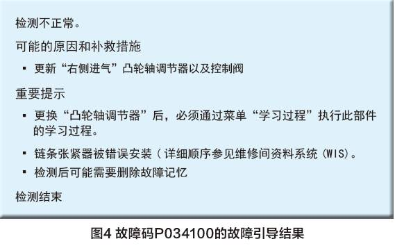
P034100 - the position sensor for the input cam axis (column 1) is malfunctioning。
P001177 - the input cam axis (column 1) deviates from the standard and does not reach the specified position。
Both fault code states are stored failures, but p034100 is the default code that caused the motivational failure lights to go off, so the failure guide for p034100 is shown in figure 4。
As the cam axle was replaced with the cam axle, the cam axle regulator was dismantled, but all of it was assembled in accordance with the guidance of the benz plant maintenance manual wis, and there was no error in the middle, and the two masters were performing the work, there was no question of an error of lower grade, but for the purpose of verification, it was performed on time and the results were normal. There was no problem with previously detected sensor lines, because the first failure code was the sensor's functional failure, which was the same as the transient cam position sensor zero, but the failure remained the same. Analysis of the two-fold barrier code, for the first time, p001685-injection cam axis 1 is untrustworthy compared to the curve axis position, with a signal above the permitted limit. And this time the failure code is: p034100 - position sensor of injecting cave axe (class 1) is stored in functional failure; p001177 - position of injecting cave axis (class 1) is out of range and cannot reach the given position。
The failure codes changed on both occasions and the results were different. Because it's "not able to reach the specified position of cam axis regulation problems" and the computer leads to the conclusion and removes the cam axis control chain for inspection. Since it was not possible to measure and check the flow of the inducted cams, which were ordered to the manufacturer by computer-directed guidance, and the control valves, each arrived with a careful examination of the cams, the control wheel, and the control valves, compared to the original car's chain, control valves, which found no anomaly, and carefully installed in accordance with the wis standards, removed the fault code and re-adapted the school, started the car, the engine went on smoothly, but the engine failure lights on the starter counter were lit, the failure codes were read, as were the second failure codes: p034,100 and p001177。
Is there a problem with accessories? Why is the problem always on the input cam axis? Once again, check the timing to make sure that there's no problem at the moment, remove the failure code and re-align the vehicle after it has started. The vehicle was activated normally, but the failure codes were still p034100 and p001177. In all likelihood, the sensor is fracturing with an oscillator, as shown in figure 5。
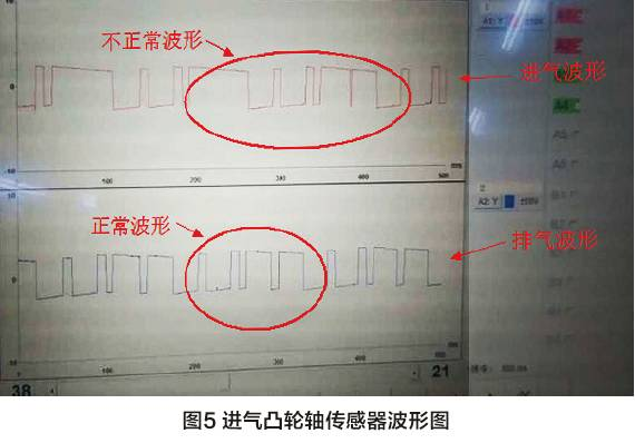
The wave-shaped figure shown in figure 5 shows that two signal wave-forms of the input cam axis are now merged, leading to sensor malfunction. The combination of signals is caused by: sensor hardware failure, sensor installation position failure, signal generator failure. Because the sensor had been replaced before, it could remove the sensor's hardware failure; because the sensor was installed in a fixed position, it measured the position of the four signal blades on the cam axis to the fixed sensor, and it showed that one of them was less than 0. 9 mm away from the other three。
It's precisely this distance of 0. 9 mm that caused an anomaly in sensor signal collection. Use tools to calibrate transformer blades, measure compliance, install sensors, remove failure codes, re-start engines, report engine failure on the dashboard, and no light. Go out and test the car. Everything's back to normal. So, the car's failure was really completely eliminated。
Maintenance summaries
When the car failed after replacing the cam axis, it over-relianceed on the diagnosis given by the computer, ignoring the meaning of the first failure code, i. E. The sensor's functional failure, and the lack of control logic of the analytical system, leading to miscalculation and the incorrect replacement of its own non-facing inductive cam link and control valves. It follows that to be a good car diagnoser, as in the case of a suspicious case, one must not let go of any clues, be precise in its analysis and seek proof in order to better and more accurately identify the real causes of the malfunction。

After reading this article, i'm actually very unhappy with myself. As a first-line technician, and a technician for high-end brand vehicle maintenance, was this the way to perform troubleshooting
As for the maintenance of modern vehicles, the use of specialized equipment has long been the same as usual, and after reading the fail code, in addition to the inspection as instructed in the maintenance manual, the use of oscillators for the verification of the failure waveforms is also a necessity, allowing for a more accurate identification of the cause of the failure, which, unfortunately, was not done by the author, and also for subsequent failures。
In addition, several issues were not clarified throughout the troubleshooting process. So i'm confused。
The first question was whether the cam axis was replaced with a flare? From the previous text, i understand that it is a single piece (which is referred to in the previous article as an excess), and i don't think the manufacturer will let it be replaced alone. What, then, is the cause of the current shift in the cam axis? Clearly, there is no answer here。
The second question is, if the parts are replaced as a whole, how can the signal blade be deformed? Are the new parts not qualified? Neither did the author
The third question is, if there's no problem with the new parts, how did the signal blades become shapeless? Is it a distortion caused by an incorrect operation? Or did you go back to the first question, where cam's axis was separate and no signal blades were replaced
The fourth question, using tools to adjust the shapeless blades, is there a special plant-specific repositioning tool? I have not heard of it, or i may be alone, but in principle the manufacturer will not provide such equipment. It's probably just a tool i made myself. I don't know if i'm right。
In any case, there are a few doubts in this article, which should be similar for readers. So, i think that this article should also explain in several respects that if it is a question of the quality of the spare parts, and it does not need to be avoided, and if it is a matter of maintenance operations, it should be preserved as a lesson to prevent similar problems from recurring。