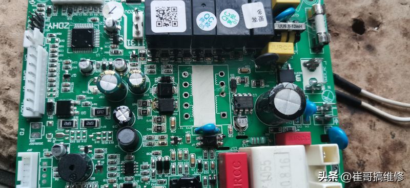
This afternoon a fan sent an instrument to hang the main panel of the gas wall. I was contacted online, said the main plate was burned, and the insurance was burned. When people see the insurance burn, they think it's better to change it. It's not that simple, or why do i need a professional?
The insurance was burned in order to prevent the escalation of the failure and to prevent fires from arising, so the safety device had to be installed。
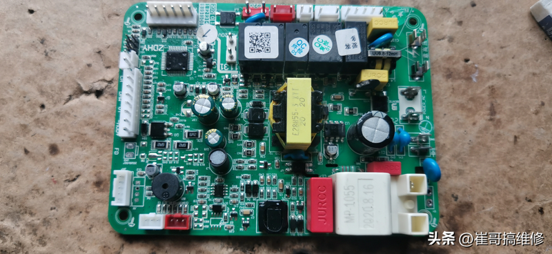
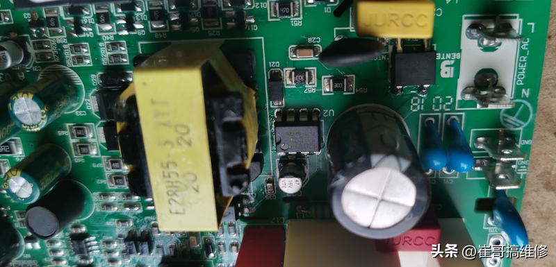
I looked at the circuit board, main plate number 1131. Insurance is no longer available and it is no longer possible to pass judgement through the collapse of the bond insurance. Another observation revealed that ntc had broken electrical resistance, suggesting that there were very serious short circuits on the circuit. Continued observation also revealed traces of fire in the primary circuit of the transformer。
Using a universal meter, it was found that the bridge blocks had been punctured, which was first dismantled and replaced with a 207s bridge。
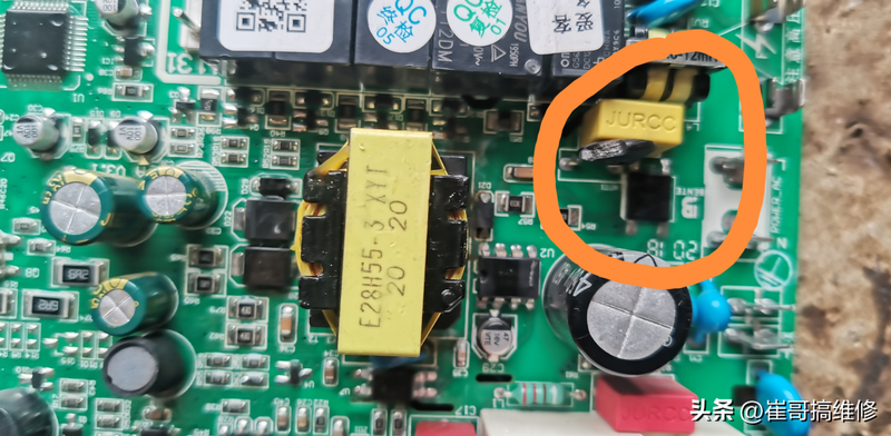
When the transformer was removed, it was found that there was electrical creeping between the initial circuits of the transformer and that the pcb circuit had struck a conductor belt. In this case, the carbide portion must be shaved with a knife and then covered with green oil。
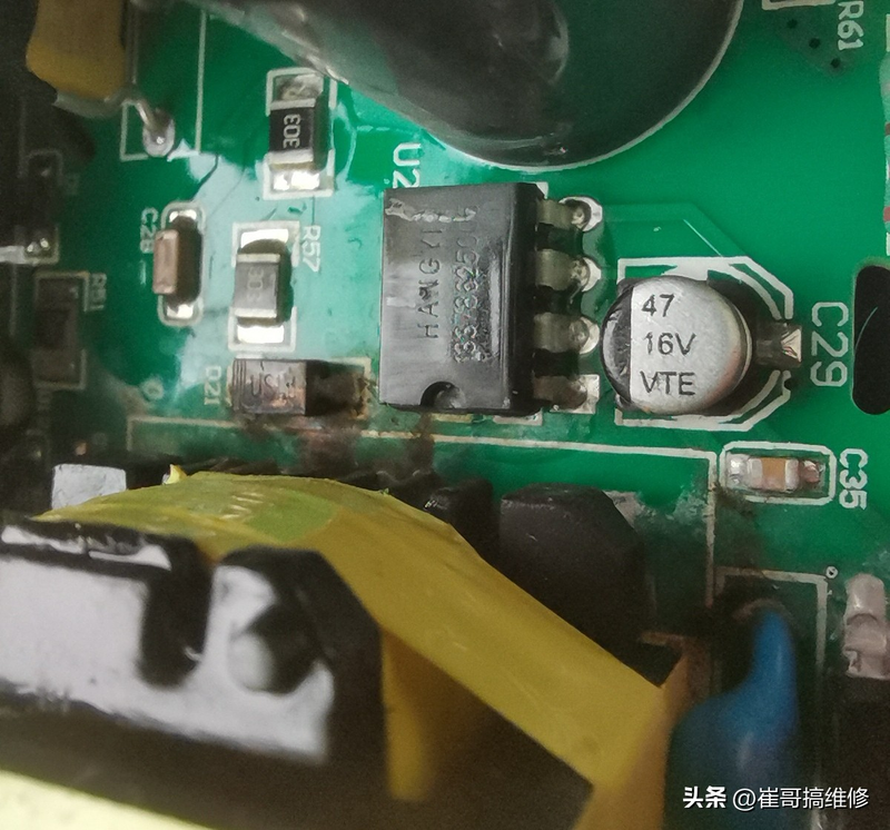
Continued measurements also found that ic was damaged, with 5678 as a lead, 12 as a lead, 4 as vcc and 3 as a feedback, but these were clearly abnormal in value, indicating that ic was damaged. Like this constant, serious fire, ic must have to be damaged。
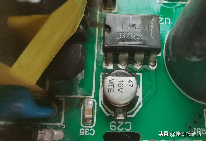
The original pwm ic marked hangyi 1337, which is clearly the seller's own logo, the true model of which is unknown。
However, this smart trig, who opened the search and entered the "chip with the switching power ic 5678"。
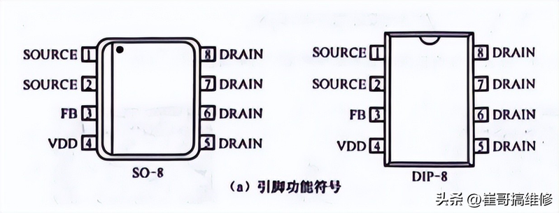
The other models can be replaced, then viper22a, after all, 22a top 20w, 12a 13w。
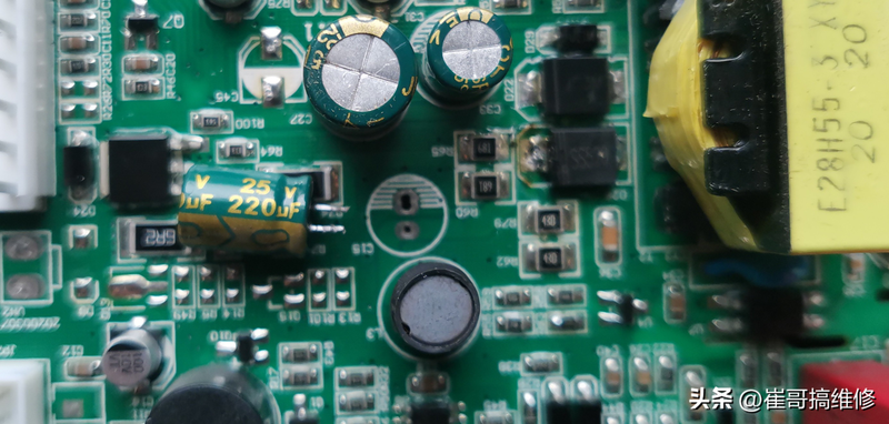
After the replacement of ic, three sub-outputs were tested, with no short circuits in the diode。
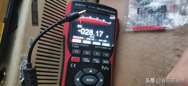
The tester was thus able to measure that there was only one type of 24v voltage in the sub-groups, and the other two, the one with no voltage value and the other with a voltage of around 3v。
Is there any problem
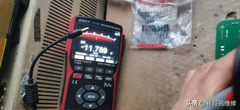
The fourth foot of the initial round is measured, the voltage is jumping, and the 9v-13v is jumping。
This secondary output voltage is unstable in the following ways:
Sub-mode 1 has short circuits, resulting in the switch power being in the cycle of opening protection and thus the secondary voltage is jumping。
2. The power side of the switch does not have a false load and the output voltage is unstable when loaded. It's just that the voltage rate is very low, and the voltage can be measured。
3. Primary feedback circuits do not have voltage delivery, resulting in insufficient start-up capacity, resulting in u2 being activated, stopped, and then activated in a renewed cycle。
Is it a problem to rule out the secondary, direct access to the +5v power supply at both ends of the c15 cap in case of power outage (because there is no information, it is not known what exactly the two ends of the cap are? The filtration tolerance values of 50 v, 35 v and 25 v for the sub-three circuit groups are assumed to be 24 v, 12 v and +5 v, respectively. However, safety considerations are tested using 5v first.) then the 34 foot resistance of the light beam is measured using a one-size-fits-all watch, while the voltage transformer is adjusted, at which time the data shown in the one-size-fits-all table can be seen to change simultaneously. This means there's no problem with secondary voltage, and it's still at the primary end。
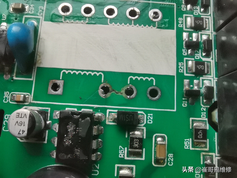
I went over the circuits and found that the previous ic did not use feedback circuits, although the transformer had primary feedback circuits, but they were not used and did not receive any components. Ic 4th gill received only one c28 (16v47uf)。
Which means the vip22a i'm replacing is still different from the prototype chip. It is impossible to find a prototype chip, but only to solve existing problems。
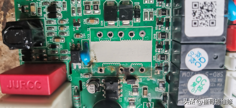
Since feedback is rounded up, it can be replaced by a diode, so that feedback rounded up c28 is powered, and the continuous supply of u2 during the u2 deadline is solved
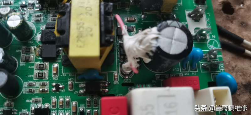
Because there were no components on the original pcb board and no circuits, i put a hole in the side of the feedback circuit, thus facilitating the welding of the feedback circuit. At the positive extreme of c28, a passkey diode m4 is then connected to the positive pole of the diode with a lead, so that the feedback group can power the c28 capacity。
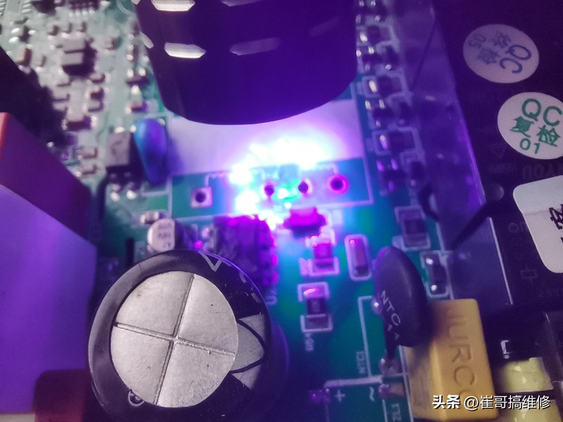
Let's check it again。
It's a big bang. It scares me. The board works。
The three sets of voltages measuring secondary output are 5v, 12v, 29v, respectively。
It's done