Slide-in-smart number oscillator usage and working principles
I. Use
The cs-cx30 smart number slider is an oscillator for imported sensitive elements. Its internal measurement system, which is based on a service (i. E. Power balance), is characterized by high accuracy, stability and resolution, and is used extensively to observe changes in levels within the earth, such as earth dams, building pits, embankments, underground construction works and rockside port works. It is the precision measurement instrument required in the observational engineering。
Ii. Main performance technology indicators。
Measurement range: 0 ~ 30° (and angles of the gland line)
System precision: ∠0. 1 mm/1000 mm system total accuracy: ∠±6mm/30m linear: ±0. 025% (within 30°) repeatability: ±0. 025% transporter spacing base: 500mm measuring rod size: ±30 x 660mm measuring pole weight: 2. 35kg
Instrument weight: 1. 5 kg (including chargeable batteries) power consumption; 20 hours of continuous use data storage: 48 g power outage data: 10 years saved environment: 20°c ~ 60°c
Anti-erosion: 150 m (*waterproof)
Earthquakes: 2000g (sensitivity axis direction, of which g is the acceleration of gravity in 1 unit)
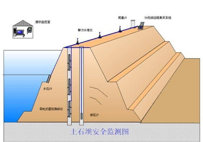
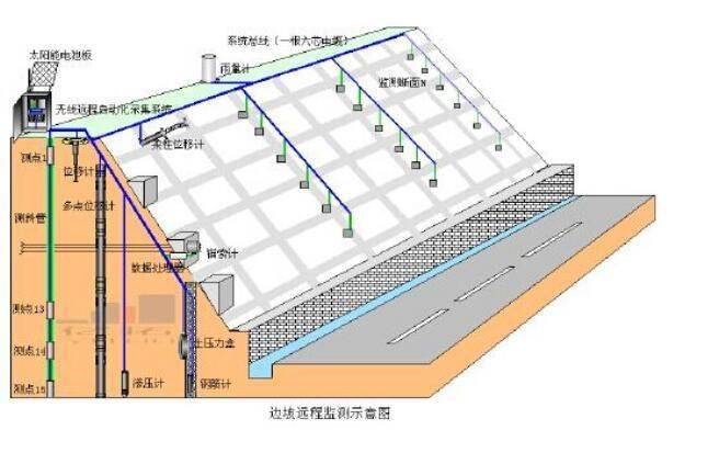
In the field of geotechnical engineering, italicometers are used primarily to measure the movement of the earth, such as those that may result in a lateral movement around the unstable slope (slide) or the excavation process. It can also be used to monitor the stability of dams, core walls, the placement and deviation of pillars or boreholes, and the sinking of earth bodies in backfills, embankments and underground tanks。
On these occasions, it is common to install an oscillating tube, either inside the underground drill or inside the main tube
They can also be laid in the embankments of concrete. It has four slots for fixed portable oscillator probes. Probes are attached to the end of a cable connected to the reading counter for the observation of vertical (or horizontal) tilts associated with the oscillation and for the measurement of any tilt changes caused by the movement of the earth。
In order to obtain a comprehensive observation of the earth around which it is installed, a series of tilt measurements along italic tubes are required. The conventional oscillating probes have two groups of sliders with a distance of 0. 5 metres. Before testing, the tube is directed and the poles are marked a+, a-, so that the calculation data are consistent. Place the probe at the bottom of the slash tube and start reading. Probes are read at 0. 5 metres per lifting until they reach the ** part of the oscillator, which is known as a+ reading (positive). Remove the probe from the tube, rotate 180° and re-place it in the oscillation tube, so as to obtain another set of data a-readers (reverse)。
When processing data, the above two sets of readings (a+, a-) are combined (one set of data minus another set of data) in order to eliminate the zero-floating effects of the inclination sensor. An oscillator detector produces a zero-floating deviation when reading at a vertical position, the ideal deviation being zero, whereas in practice, when using a probe, there is a zero-floating value as a result of the sensor's deviation, the wear of the slider, or the impact on the sensor by falling and touching the bottom of the oscillation tube。
The next oscillation tube observation data, when compared with the original observational understandings, can be seen both in terms of the slope changes and in the position they cause. A better way to analyse tilt changes is to calculate the horizontal deviation of the margin between the upper slider and the observed reading (l) from the inclination (thirty) generated by the lower slider group. Two sets of readings (a+, a-) can be derived by decreasing at each oscillation position, multiplying the value by the reading space (l) and the corresponding coefficient, resulting in a horizontal deviation from output in engineering units (mm as shown on dgk oscillation)。
In parallel with data processing, data reliability analysis should be carried out, usually by “checking and” adding up two sets of readings (a+, a-), offset by the additional portion caused by tilt, leaving only one value equal to twice the zero deviation of the oscillator sensor, expressed in the north flight software as the “margin” item, indicating that the measured data are more reliable when the check and value or the “margin” item in the software is constant, and, in the reverse, indicating that measurement data are problematic if the margin changes softly or mutationally
Slider oscillator structure and working principles
1 structure
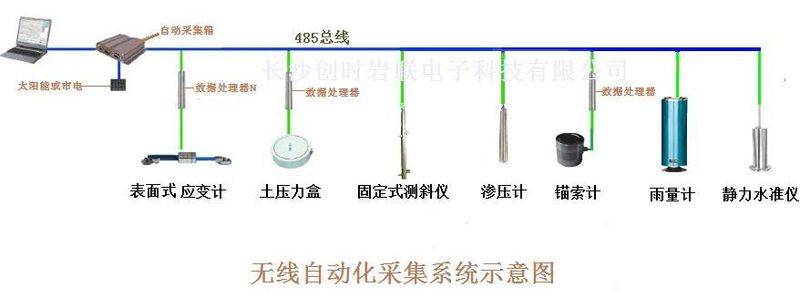
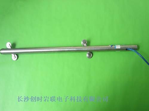
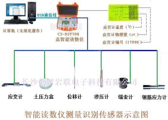
Cs-cx30 is composed of tilt sensors, poles, directional locators, signal transmission cables, cable boxes and rodboxes, which can be used by the company to produce intelligent collection systems to read measurements and transmit measurements to computers。
2. Rationale
An oscillation tube is placed on structural objects requiring observation, with two pairs of guidance slots of 90° each in the inner diameter of the oscillator, which are placed in the oscillation tube and measured by a base length (conductor spacing). The measurement data can be calculated to describe the curves in which the oscillation line is deformed with structural matter, which allows the horizontal shift of the axial line on each base length from the lead plume。
Array formulas and data principles
1 conversion factor per voltage
Because the output voltage is proportional to the sine of the inclination。
Voltage u = ksin (k = tilt angle and k = sensitivity factor for oscillating probes)
Offset d = l. Sinθ (l/k) = u = c. U. C.: probe voltage one-to-one conversion factor (slash probe factor)
The slasher works:
In the field of geotechnical engineering, italicometers are used primarily to measure the movement of the earth, such as those that may result in a lateral movement around the unstable slope (slide) or the excavation process. It can also be used to monitor the stability of dams, core walls, the placement and deviation of pillars or boreholes, and the sinking of earth bodies in backfills, embankments and underground tanks. On these occasions, it is common to install an oscillating tube, either inside a drill under the ground or in a concrete structure, or to bury the tube in an embankment. It has four slots for fixed portable oscillator probes. Probes are attached to the end of a cable connected to the reading counter for the observation of vertical (or horizontal) tilts associated with the oscillation and for the measurement of any tilt changes caused by the movement of the earth。
The stationary tiltors, which are used in places where the conventional portable italics are difficult to read in situ, as well as in remote deformation monitoring of data from various rock and earth bodies and steel structures, are widely used to measure vertically (transformation) or horizontally (leaving) changes in the direction of the base or structure, e. G., long-term burial in a hydraulic or other concrete building (e. G., on the shore of the port), upper buildings, underground buildings, tunnel condensation, bridge arches, deformation on the inside or on the surface, etc. This type of product series is structured in a variety of forms, and can be supplemented by different installation attachments to adequately meet different installation needs。
The product series has the following characteristics:
1. Vertical surfaces installed, boreholes installed, tunnels constricted, bridge arch deformation monitored, and extensive use. 2. Long-term stability and superior water protection。
3. High reliability, full import chips, smd advanced process production。
4. Advanced mems (micromechanical) principles, high sensitivity and low temperature drift. Full digital signal output, internalizing wave-proof circuits to support interface heat-plugging. 6. The curve is to be calibrated with high relevance and small error。
The slasher works
Accelerometers of imported quartz accelerators are primarily used as sensitive components, which are a force-balanced servo system, where the sensor produces an arctic accelerator relative to the earth's gravity direction, and because of gravity, sensitive elements in the sensor move an angle relative to the direction of the lead hammer, which is converted to a signal through a sensitive quartz exchanger, which, after data analysis, can be used directly to show the horizontal movement of the detected point。
Sensitivity components are made of molten glass near zero temperature coefficients, with high accuracy, stability, repetition, low drift and high heat stability. Originally used mainly for navigation on spacecraft, in recent years, due to reduced costs, it has been used as an oscillator, produced in accordance with ** production standards and with high reliability. The design of the instrument was significantly improved on the original basis, with better sealing and easier handling. Also, high-intelligence electro-slashers have access to automated monitoring systems similar to those of other high-intelligence sensors in the same way as in the same way as technology
Slider slasher working principles
In the field of geotechnical engineering, italicometers are used primarily to measure the movement of the earth, such as those that may result in a lateral movement around the unstable slope (slide) or the excavation process. It can also be used to monitor the stability of dams, core walls, the placement and deviation of pillars or boreholes, and the sinking of earth bodies in backfills, embankments and underground tanks。
On these occasions, it is common to install an oscillating tube, either inside the underground drill or inside the main tube
They can also be laid in the embankments of concrete. It has four slots for fixed portable oscillator probes. Probes are attached to the end of a cable connected to the reading counter for the observation of vertical (or horizontal) tilts associated with the oscillation and for the measurement of any tilt changes caused by the movement of the earth。
In order to obtain a comprehensive observation of the earth around which it is installed, a series of tilt measurements along italic tubes are required. The conventional oscillating probes have two groups of sliders with a distance of 0. 5 metres. Before testing, the tube is directed and the poles are marked a+, a-, so that the calculation data are consistent. Place the probe at the bottom of the slash tube and start reading. Probes are read at 0. 5 metres per lifting until they reach the ** part of the oscillator, which is known as a+ reading (positive). Remove the probe from the tube, rotate 180° and re-place it in the oscillation tube, so as to obtain another set of data a-readers (reverse)。
When processing data, the above two sets of readings (a+, a-) are combined (one set of data minus another set of data) in order to eliminate the zero-floating effects of the inclination sensor. An oscillator detector produces a zero-floating deviation when reading at a vertical position, the ideal deviation being zero, whereas in practice, when using a probe, there is a zero-floating value as a result of the sensor's deviation, the wear of the slider, or the impact on the sensor by falling and touching the bottom of the oscillation tube。
The next oscillation tube observation data, when compared with the original observational understandings, can be seen both in terms of the slope changes and in the position they cause. A better way to analyse tilt changes is to calculate the horizontal deviation of the margin between the upper slider and the observed reading (l) from the inclination (thirty) generated by the lower slider group. Two sets of readings (a+, a-) can be derived by decreasing at each oscillation position, multiplying the value by the reading space (l) and the corresponding coefficient, resulting in a horizontal deviation from output in engineering units (mm as shown on dgk oscillation)。
In parallel with data processing, data reliability analysis should be performed, usually by “checking and” adding two sets of readings (a+, a-), offset by the additional portion caused by tilt, leaving only one value equal to twice the zero deviation of the oscillator sensor, expressed in the north flight software as “margin” item, indicating a higher reliability of the measured data when the check and value or “margin” item in the software is constant, and, in the reverse, indicating a problem in the measurement data if the margin changes softly or mutationally:
-/gbabcej/-
Http://lzy110. B2b168. Com