The core of the dpt type is functional matching and parameter threshold locking, which requires a professional technical definition of the two core types of resistance, eliminating performance failures caused by generic cross-product substitution, and providing the basic framework for subsequent submodule selection, following the principle of standardized selection。
(i) boundary definition of two core electrical resistance technologies
1. High-accuracy sup film electrical resistance is a pre-deployed acoustic circuit specialty designed to meet resistance accuracy of 0. 1%, with a level-matched accuracy of 0. 05%; temperature factor tcr≤±10ppm/°c, grade tcr≤±5ppm/°c; voltage noise density <10nv/√hz@1khz; sensory design esl <1nh; anti-sulphide level ≤±4 and long-term stabilization of resistance values of 0. 05% at 1000h/70°c, which is the only appliance group for core acoustic circuits such as front-level dac decoding, transport amplification, integrity loop feedback。
A column power resistance is a power-grade and circuit-protected specially designed device with an axle ceramic seal + complete sensory design, covering three main types of non-discretionary wire, metallic oxidation membrane and thallium ceramics; power-scale applications need to meet electrical sensor < 50nh, add <30nh; temperature factor tcr≤±100ppm/°c, with preference of ±50 ppm/°c specification; rated power needs to be set at peak power consumption by more than 3 times the excess; insulation tolerance > 500v, fitting power tube average flow, output-retarded nie, limit-to-flow protection, power-to-soft start, high power, instant impact applications。
(ii) the principle of universal selection of resistance to discharge
1. The principle of priority for circuit function: high-precision membrane resistance is preferred for front-stage signal processing and decoded modules, power magnification drives, system control protection, power supply modules must opt for total non-sensor column power resistance, and cross-species and cross-functional substitution is strictly prohibited
2. Parameter redundancy design principle: power parameters are 3 times the function of the actual peak, stress tolerance parameters are 2 times the actual working voltage, and temperature drift parameters are combined with the working temperature range of the working unit - 40°c ~ 85°c to account for resistance drift to ensure stability of the parameters under the overall work condition
3. The principle of batch consistency control: the requirement for acoustic consistency in the acoustic multi-channel performance is stringent, and the need to ensure that the same-type, simultaneous-channel resistance is produced in the same series, with a difference of 0. 02 per cent in the accuracy of the same batch and 2 ppm/°c in tcr deviations to avoid an imbalance in the acoustic performance resulting from the dissipation of the plant parameters
4. Hf characterization principle: power release requires the achievement of 20 hz ~ 20 khz full-band non-fiscence output, supported by electrical resistance with high frequency sensory and low parasitic capacitor properties, equivalent to a series of electrical conescapsulations esc < 0. 5 pf, and the elimination of high frequency interactivity, signal reflection and self-stimulation。
Ii. High-precision sticker film resistance: pre-accuracy circuit module selection techniques points
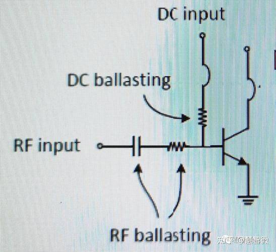
The front-stage signal processing and decodering module, which is the core of the decision-making sound quality, with its core claim of low noise, low drift, high matching, high stability, needs to be structured around four core requests, combining the functions of the dac decoded, amplified, closed looped feedback, fine sampling, etc., and setting parameters thresholds, ultimately achieving the technical objectives of the whole machine base noise <-95db, audio gain difference < 0. 1db, 20hz ~ 20khz frequency flat ± 0. 5db。
(i) dac decoded and lpf circuit selection
Dac decoding and low-left wave circuits are the core elements of the conversion of digital audio signals to analogue signals. The resistance parameters directly determine the precision of the digital model conversion, the impurity of the impurities and the purity of the signal, as well as the subdivision circuits that require the highest pre-valuation resistance selection. In this circuit, the i/v conversion resistance matching the differential output is subject to the selection of a high-precision plate film resistance with a resistance accuracy of ±0. 05 per cent, tcr=5ppm/°c and a deviation of <0. 01 per cent from the resistance; low-access filter network resistance accuracy of 0. 1 per cent, tcr±10ppm/°c. Full circuit electrical resistance is required to meet voltage noise density <8nv/√hz@1khz, unsensible design esl <0. 8nh, anti-sulphurization level 4 and above, adapt to the long-term high-temperature and wet working environment at the front stage of the function and eliminate the failure of sulphurization; containment is preferred to 0402/0603 specifications to meet the design needs of the front-level circuit mini-design, with a rated power selection of 1/8w ~1/4w, and adapt to the small signal at the front stage and low-capacity work characteristics。
(ii) release magnification and gain setting circuit selection
Spread magnification and gain setting circuits determines the increase accuracy, acoustic consistency and signal transfer linearity of the operation, and electrical resistance selections need to match accurately the input characteristics of the delivery and avoid a failure to resist a signal reflex and non-linear distortion resulting from mismatch. In the circuit, the resistance value for the same/reverse end matching resistance, closed loop feedback resistance, and enhanced calibration of resistance is 0. 1 per cent, and must be guaranteed in the same series, tcr ≤±10ppm/°c, with the same batch tcr deviation 2 ppm/°c; the resistance label needs to match the anti-precision value of the discharge resistance, with a preference of 10 k ~ 100 k resistance range, avoiding resistance to deviation > 5 per cent. At the same time, electrical resistance is required to meet the long-term stability requirement of 1,000 h/70°c resistance to drifting ≤±0. 05%, ensuring greater stability and non-acoustic decay in the long-term work of the performance; and the strict prohibition of the use of normal membrane resistance of ±1% and above accuracy, which can lead to increased drift, disequilibrium imbalance, and ultimately to a general acoustic sound system's positioning deviation。
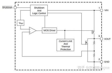
(iii) closed ring negative feedback circuit selection type
The core function of the closed loop negative feedback circuit is to lock in the rated gain of power discharge (26-30 db), stabilize power-level static work points, while inhibiting temperature drift and large signal distortion, and the electrical resistance type needs to balance the three core requirements of accuracy, shock resistance and low drift. Closed loop feedback in the circuit, feedback on downside resistance, differential input level long tail resistance, resistance accuracy of 0. 5 per cent, preferred ± 0. 1 per cent high precision specification, tcr ≤±10 ppm/°c, avoids the loss of electrical resistance values due to power-grade heating during power release work, which in turn triggers a power-grade static work point out of control. Electrical resistance is required to meet the 1,000 v/1 ms pulse shock test, which is resistant to instant voltage fluctuations at the power-receiving level, barrier-free mutations, performance failure; and rated power is selected using 1/4w ~1/2w specifications, with a reasonable power surplus, with a slight power-resilient fluctuations during the fitr closed loop. This circuit is strictly prohibited from using normal thick membrane electrical resistance, and its thermostatic currents, which run out of control at the power level, cause the power pipe to burn in severe cases and significantly increase the back-up rate。
(iv) precision sample circuit selection type
Precision sampling circuits provide a precise sampling signal for the power voltage, overall temperature and working currents of the cmu, which is the system-protected signal source of the electrical circuit, with a resistance core of high resistance, low drift, high linearity, which directly determines the trigger accuracy and reliability of the circuit. Mcu adc in the circuits takes a fractional charge of electrical resistance, overflows protect a precise sample resistance, with a resistance value of 0. 5 per cent and tcr ≤±25ppm/°c to ensure the linearity and accuracy of the sampling signal and avoid a sampling deviation due to non-linear distortions. Resistance rated pressure needs to be more than 2 times the actual power voltage installed at the power source, and the specification for the power source sample sample resistance pretense 400 v, with a rated power of 1/4 w ~1/2 w; and within the full working current range, the resistance value linear deviation < 0. 1 per cent ensures that the sampling signal corresponds accurately to the actual performance. The use of generic carbon membrane resistance with low resistance and high temperature drift is strictly prohibited, and such resistance is prone to electro-pressure penetration, which can lead to severe deviations in the sampling signal, which eventually triggers or does not trigger the protection of the circuit and loses the protection of the entire machine。