1. Rationale and location of installation
Compressors are the heart of the refrigeration system and consist of electrical and compressed parts. The electron is activated to boost the compression component to transform the low-temperature, low-pressurant gases inhaled by the gas pipe into high-temperature, high-pressure gases. Common compressors are mainly piston, rotation, vortex。
1 pistol compressors are mainly used as cabinet-based air conditioners for the early three-phase power supply and are not currently in use。
2 turbo compressors are primarily used for 3p or 5p-box air conditioners, which are currently powered in the three-phase。
3 the most common is a rotary compressor, which is usually a single-stage, 220v-powered air conditioner, which is rotated, so the contents of this section are mainly rotated。
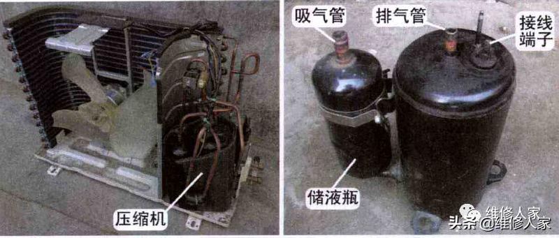
The compressor is installed on the right side of the outdoor machine and is secured on the outer floor. Among them, compressors connect to the electrical control system, and gas and vents connect to the refrigeration system。
The figure below shows the physical shape of the rotary compressor, with interfaces such as gas straws, vents, wiring terminals, liquid storage bottles, etc。
2. Method of identifying the concourse or ender function of compressors
There are three common methods, i. E., the use of a tensile surface block to measure the wiring or end-of-wire resistance, based on the actual assembly element of the compressor fuse, and the identification of the compressor lid or gasket。
1line function based on actual connection
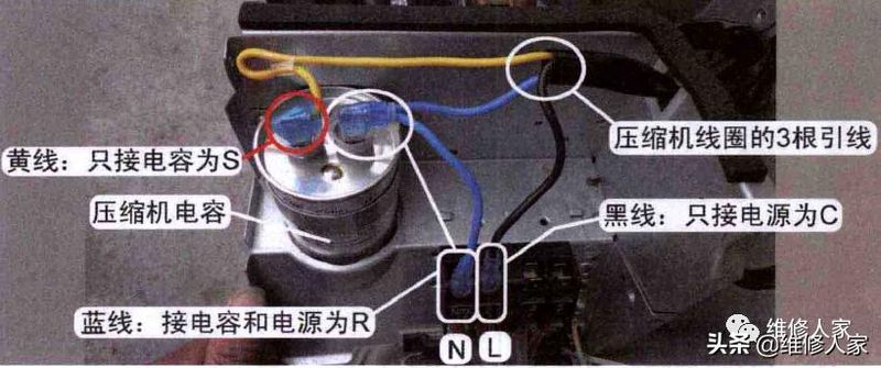
There are three wires on the compressor's lock and only three lines on top, so that only three lines connect to the electrical control system。
See figure below, black wire only connects to the main end of the line, at the end of the power source l-2 for the public end (c); the blue line to the power line and to the power source n-1 for the operation of the circuit (r); and the yellow line to the power only for the initiation of the circuit (s)。
2 to measure the end of the circle using a tens of thousands of meters
The three endpoints of the compressor are measured on a case-by-case basis, resulting in three different results. When the shanghai-based sd145uv-h6au compressor is at an outdoor temperature of about 15°c, the measured barrier is 7. 3 times, 4. 1 times, 3. 2 times, and the resistance relationship is 7. 3 = 4. 1 + 3. 2, i. E. The maximum barrier of 7. 3 times is the operating circuit plus the total of the block value of the start-up circuit。
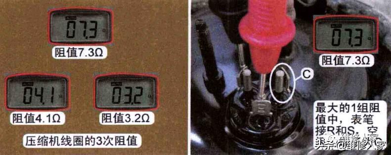
Identify the public end: of the maximum barrier 7. 3 times, the end of the desk is the start of the bypass group and the running of the circle group, and the free end is the public end (c)。
Note: when determining the function of the end of the line, the line is measured by measuring it, instead of opening the header and removing the lead plug to measure the end of the line. Only by replacing the compressor or compressor connection will the barrier of the end of the line be measured to determine the function。
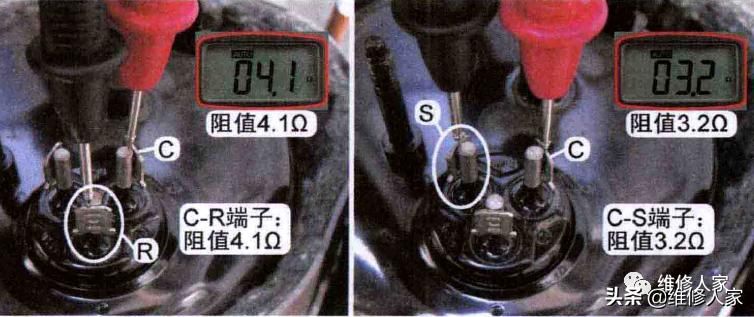
Finds the running and starting circuits: 1 table of pens to the public end (c), and 1 table of pens to measure the other two end blockes, usually the lower end of the barrier is the running loop (r) and the larger end of the block is the start circle (s). However, the main endpoint (4. 1 times) measured by this machine is the operating circuit group (r) and the small endpoint (3. 2 times) is the activation circuit group (s)。
3 based on compressor cord or gasket identification
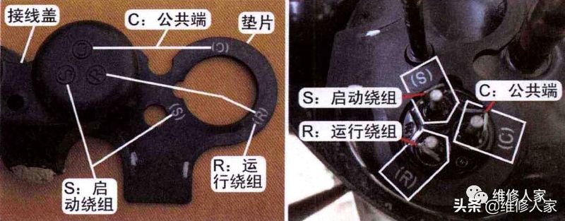
Compressor lids or gaskets (using heat resistant materials) are marked with the words "c, r, s" for the function of the main end of the line: c is a public end, r is a run circuit, and s is a starter。
The main end of the line, or the fixed position in which the gasket is installed on the compressor, is observed: the end marked with "c" is the public end, the end marked with "r" is the running circuit, and the end marked with "s" is the starting circuit。
3. Measuring three-phase electrical compressor loop resistance
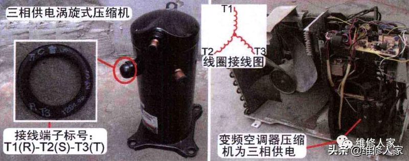
Turbo compressors with three-phase power and transformer air conditioners with three-phase cables. Three-phase compressors have three circuits inside, three of which have the same wiring and wiring, so that the three circuits have equal resistance values. A compressor with a three-phase power supply also produces three lines, usually marked t1(r or u), t2(s or v), t3(t or w)。
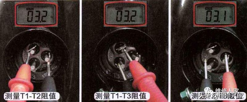
The measurement process is shown in the figure below, where the barrier between the three endpoints of the line, t1-t2, t1-t3 and t2-t3, i. E. T1-t2=t1-t3=t2-t3, is measured using a stand-alone block, which is about three times。
4 measuring end-to-ground resistance
The most common reason for the failure of the air conditioner to jump or to jump is the short ground-to-ground circuit of the compressor. The method of detection is to measure the end of the line and the value of the ground (extra compressor, copper tube, exterior steel skin) using a universal electrical block, which should normally be infinity。
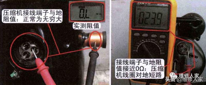
The compressor shall be replaced if the resistance is measured 0 times or close to 0 times (under 2m times), indicating a short ground-to-ground circuit of the compressor's circle。