Summary: the application of the traditional single tube is limited by the weight of the space-to-float restriction caused by the re-entry of magnetic cores, and mosfet is limited by input of two times or more power voltage, while the two-barrel is widely applied in medium-power circuits with such advantages as low switch-to-pipe voltage, direct access to non-bridge arms, high reliability and no need for additional magnetic core re-routing. A medium power (200 w~500 w) two-barrel positive transformer model was built on the saber software platform, and online real-time simulations and modifications of the built-up transformer model were eventually more satisfactory. The simulation results not only validate the advantages of the two-barrel positive transformer described above, but also indicate that the model has a significant effect on reducing the development cycle and design costs。
Keywords: double-barrel positives; magnetic core compounding; saber
0 introduction
The single tube is an engine transformer with simple structure, reliable work, low cost, etc., but the high frequency transformer must be removed from the magnetic repositioning during the switch break, and must therefore be added to the magnetic circuit group or rcd, which, together with the rcd, will result in greater energy loss and decrease the efficiency of the transformer。
This paper adds a low power mosfet and two high-pressure low power diodes to the single-barrel dynamic to complete the magnetic fluxing position of the transformer and returns the energy stored in the sensor to the input end without power loss, thus increasing power efficiency。
1 transformer circuit model
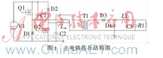
Figure 1 shows the basic model of the two-barrel positive transformer circuits, with q1 and q2 being high pressure low power mosfet; d1, d2 being internal q1 and q2 parasites; d3 and d4 being energy storage and transmission for output integrator and continuous diodes; t1 being a high frequency transformer for separation and pressure relief; lp being a pre-frontal circuitr sense; and ls being a sub-side circuitr. At high pressure mosfet-q1 and q2, energy is released through d1 and d2, while np's leakage is returned to input via d1 and d2 so that no repositioning groups are required for the primary transformer。
2 calculation of key parameters
2. 1 circuit design specifications
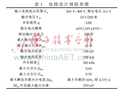
Circuit design specifications are shown in table 1。
2. 2 high frequency transformer parameter selection
(1) identification of transformer model
The high-frequency transformer magnetic core model, which corresponds to the output power and working pattern, is first selected, taking into account cost considerations, and the pq32/30, ap = 2. 408 6 cm4 (ap-value magnetic core specification table based on the experience formula)。
(2) request for comparison
The initial grade ratio of the transformer is obtained by the formula。
(3) ccm magnetic stress lmag
Lmag=5. 495 mh is used to calculate the minimum electrons required for the original boundary from experience and related formulas。
(4) calculation of initial grade
It was calculated that the original rounding number would be 50 and the secondary rounding group would be 12。
2. 3 high pressure mosfet selection
The power tube q1 and q2 can select 800 v power mosfet, which can be calculated by the transformer's maximum primary peak of 4a, with appropriate sufficiency and power expansion, and therefore the fqa7n80c power tube of 800 v/7a。
3 converter saber model simulation
3. 1 introduction to saber
Saber is an eda software of the united states company synopsys, which provides a powerful hybrid emulator for complex hybrid signal design and validation that addresses a range of issues ranging from system development to detailed design, validation, etc. Saber contains a rich model bank, particularly a rich transformer model, compatible with the extension of the spice model, and is therefore well suited to switch power and to simulations containing pfcs. This paper makes full use of saber software to build relevant models in its software and achieves better control effects。
3. 2 converter simulations
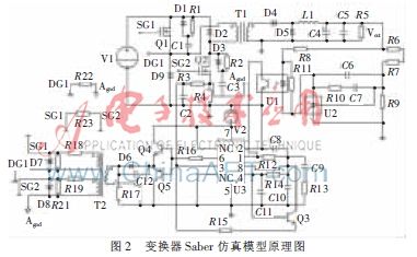
The switch power control chip uses the more common uc series of current-wire control chips in saber, bringing the power system down from level two to level one, leaving the system free of conditional loop stabilization problems. At the same time, since the double tube is excavating in the space ratio d<0. 5, there is no need to add magnetic core retort groups to the single tube. The system simulation model is shown in figure 2。
3. 2. 1 maximum load of minimum input voltage
Set v1 = vin = vinmin = 265 v, load r5 = 242/200 = 2. 88 times, figure 3 is mimic. In the figure, the pwm wave signal, which is driven from top to bottom by q1, q2, the original side of the transformer's magnetic electromagnetic sensor signal, the upper arm's q1-vds signal, the internal parasitic diode d1 and the transformer's primary current signal。
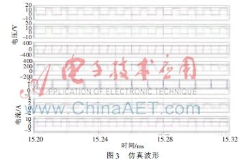
As can be seen from figure 3, the two-way drive signal meets the two-barrel positive-strength command signal requirement, with a maximum driver range of 14. 716 v, a switch frequency of f=102. 26 khz, and a maximum space ratio broadly consistent with the design, justifying the correct design。
Figure 4 shows output voltage and output current wave shapes。
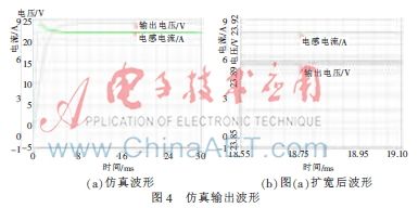
As can be seen in figure 4 (a), output voltage and electrons current-form dynamics and static performance are good (10 ms is stable); and as shown in figure 4 (b), main route 24 v output 23. 898 v, all voltage-coated waves are within 10 mv, meeting the design accuracy requirement of 150 mv, and electrical current-cording of 53. 6 ma, meeting the design accuracy requirement within 100 ma。
3. 2. 2 full rated voltage
Sets vin = vinnom = 311 v, 24 v load 2. 88 times on main route, and figure 5 is a simulation of the output wave shape. In the figure, the pwm wave signal, which is driven from the top to the bottom by q1, q2, the electromagnetic sensor signal on the side of the transformer, the q1-vds signal on the upper arm of the bridge, the internal parasitic diode d1 and the transformer's primary current signal。
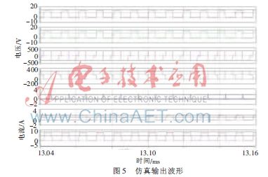
As can be seen from figure 5, the two-way drive signal meets the requirements for a positive-drive signal, with a maximum drive band of 13. 961 v, a switch frequency of f=103. 24 khz, a maximum space ratio of 0. 408 23, and a maximum power tube tolerance peak of 31. 85 v。
Figure 6 shows output voltage and output current wave shapes。
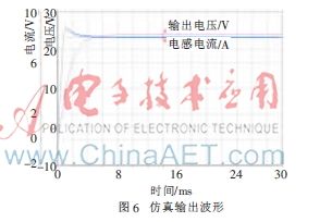
As can be seen from figure 6, the main route 24 v output 24. 005 v, current output 8. 020 8 a, voltage texture waves within 10 mv and 58. 49 ma meet the design precision requirements and reach a steady-state time faster than a low-pressure full load, around 11 ms。
3. 2. 3 maximum working voltage light load
Sets the input of a maximum working voltage of 360 v, with a main road load of 100 times, i. E. A load of 6/200 = 1/30 (slightly small), to test the light load properties of the transformer, and figure 7 is a simulation of the output wave shape. A pwm wave signal driven from the top to the bottom by q1, q2, a voltage voltage signal at the front edge of the transformer, a q1-vds signal for the upper arm of the bridge, an internal parasitic diode d1 and an initial voltage signal for the transformer。
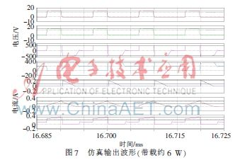
As can be seen in figure 7, the 2-way drive signal meets the two-barrel positive-strength command signal requirement, with a maximum driver range of 14. 017 v, switch frequency f=101. 66 khz, with a minimum space ratio of 0. 313. 63. Power tubes bear a maximum peak of 360. 79 v, close to power voltage。
Figure 8 shows the pwm wave shape, the output voltage and the current wave shape of the output band in different loads。
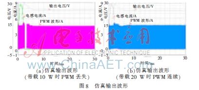
Figure 8 (a) and (b) shows that the system works in the dcm mode at high pressure light and that the output voltage is overstretched, while the output sensor current will also have a dead zone of 754 μs (i. E., during the loss phase of the pwm wave, the dead zone increases as the load is reduced). Table 2 is the value of the output voltage and space ratio corresponding to 6 w-30 w when imitating load data。
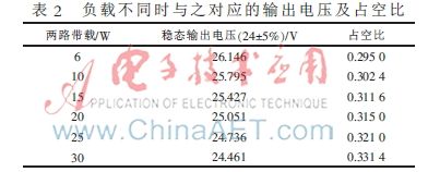
As a result, double-barrel positives are not suitable for work in light and empty environments and should normally be carried with a false load, as in the case of the design of this paper, with a false load of 20 w (i. E. The designer is required to debug the minimum space ratio to be met at the lightest load under the maximum input voltage)。
Conclusion
In general, double-barrel power is simpler than a single tube, magnetic double-bit voltage is equivalent to input voltage, and the maximum space ratio is therefore limited to less than 50 per cent, and there is no single-barrel active core co-location problem, with high reliability, not only expanding the range of choices of switches and their load power, more conducive to the design of the dispersive system, less consideration of the effects of accurate magnetic stimulation and leakage, and is highly adaptable to the medium power level, so that the converter is well suited to high-pressure input and high-precision power systems, but works in a certain load situation and is not well suited to work in a space or light load。