External and domestic electromagnetic valves are classified in principle (i. E., direct, step-by-step, lead), while differences in structure and materials from valves and principles are divided into six branch subcategories (direct motion film structure, step-by-step weight structure, lead membrane structure, direct thrust plug structure, step-by-step piston structure, lead piston structure)。
Direct electromagnetic valves:
Principle: when electrically activated, the electromagnetic circle produces electromagnetic power to lift the closure from the valve and open the valve; when electricity is cut, the electromagnetic power disappears, the spring presses the closure on the valve and the valve closes。
Characteristics: normal working at vacuum, negative pressure, zero pressure, but generally not exceeding 25 mm。
Distribution of direct motion electromagnetic valves:
Principle: it is a combination of direct motion and lead, and when there is no discrepancy with the export, the electromagnetic force lifts the lead valve and the main valve directly up and opens the valve. When the difference with the export trigger pressure is reached, the electromagnetic power leads to the small valve, the lower cavity pressure of the main valve rises and the upper cavity pressure drops, thus pushing the main valve upwards using the pressure difference; when the power is cut, the lead valves use spring power or medium pressure to drive the closure, move downward, and close the valve。
Characteristics: it can also be actionable at zero pressure differentials or vacuums, but with greater power and requires horizontal installation。
Lead electromagnetic valves:
Principle: when electricity is powered, the electromagnetic force opens the lead point, the upper chamber pressure falls rapidly, the upper chamber pressure forms a low and high pressure differential around the shutter, fluid pressure drives the shutter up and the valves open; when the power is cut, the springs close the lead point, the pressure creates low and high pressure differentials around the closeer through the perforated rapid chamber, and the fluid pressure drives the shutter down and closes the valve。
Feature: fluid pressure range caps are high and can be installed at will (to be customised) but meeting fluid pressure differential conditions
I. Structure classification of three electromagnetic valves
Three electromagnetic valves control the valves mainly through currents through the wires in the electromagnetic valves, and three of the structures of the three electromagnetic valves are divided into one, two, one, and one. This is followed by a brief presentation of the working principles of the three three electromagnetic valves. The working principle is that an electromagnetic valve controls the mouth, one opens and one closes when the wire of the electromagnetic valve goes through. When the electromagnetic valve is out of power, the switch on the mouth is in the opposite order as when the power is out. The second two-in-one operation is that the electromagnetic valve controls the vent when the wiring of the electromagnetic valve goes through. When the electro-magnetic valves are out of power, the opening order of the vents is the opposite as when the power is activated. In the third comparison, the three electromagnetic valves are divided into two scenarios, one entering and the other entering and the other entering and the other (the usual) working on the principle that the interface a leads to interface b when the wires in the electromagnetic valve go through. When the wire in the electromagnetic valve is out, interface a is automatically shut and interface b leads to interface c. As soon as it enters and exits (on a regular basis), the principle is that when the wires in the electromagnetic valves go through, the interface c leads to interface a, which automatically closes. When the wire in the electromagnetic valve is out, interface c is automatically shut and interface a leads to interface b。
Ii. Rationale of three electromagnetic valves
The creation of three electro-magnetic valves has made life easier by effectively controlling the transmission of a range of substances, such as water and air currents, thus avoiding unnecessary waste, and it is believed that three electro-magnetic valves will also be more widely applied in a wide range of areas and that their use will save energy. Effective efficiency gains through the timeliness of control valves. It is therefore quite wise to choose the use of three electro-magnetic valves, especially if they are effective in preventing the erosion of strong acid alkalis and are sustainable in the system. In this way, the durability and utility of the three electro-magnetic valves is more assured. Three electromagnetic valves will increasingly be applied in facilities and construction。
The effective control of three electromagnetic valves has resulted in significant savings in production costs for the plant, and three electromagnetic valves have functioned as a diversion of materials and have greatly enhanced their efficiency. Human, material, etc. Have been saved, and more and more can be seen in the shape of three electromagnetic valves in future lives。
Attention of electromagnetic valves in the selection process
I: applicability
The fluids in the pipe are consistent with the medium selected for the emp series type。
The temperature of the fluid is smaller than the rated temperature of the selected electromagnetic valve。
Emps allow liquid viscosity to be generally below 20cst and greater than 20cst。
(a) work pressure differentials, with piped high pressure differentials of less than 0. 04 mpa, choosing a direct and step-by-step motion pattern such as zs, 2w, zqdf, zcm series; electro-magnetic valves with low work pressure differentials of more than 0. 04 mpa; and high work pressure differentials less than the high standard pressure of the electromagnetic valve; the general electromagnetic valves are one-way jobs, so care is taken whether there is an anti-pressure differential, if any。
Filters should be installed in front of the electromagnetic valve when the fluid is less clean, and general electromagnetic valves require a better level of cleaning of the medium。
Pay attention to flow apertures and take-over calibres; electromagnetic valves are generally controlled only by two switches; conditions permit the installation of bypass tubes to facilitate maintenance; and when a water hammer phenomenon occurs, the timing of the opening of the electromagnetic valve is customised。
Pay attention to the effect of ambient temperature on electromagnetic valves
Power currents and power consumption should be selected on the basis of output capacity, with power voltage generally allowed to be around 10% and va values higher when communication starts。
Reliability
Electromagnetic valves are divided into two types of constant closed and open; it is generally selected to be closed, open and shut down; however, it is chosen to be open at a short time when the opening time is long。
The life-cycle test, which is generally a model pilot project, is not exactly the standard for electromagnetic valves in our country and is therefore carefully chosen for the use of electromagnetic valves。
When action time is short and relatively high, it usually selects a direct motion pattern and a fast series with a large calibre。
Iii. Security
General electromagnetic valves are waterproof and, when conditions do not permit, choose a waterproof type, which can be arranged by the plant. The high-standardised generic pressure of the electromagnetic valve must exceed the high pressure in the tube, otherwise the useful life will be reduced or other contingencies will occur。
For corrosive liquids, the total stainless steel type should be chosen, and the powerful corrosive fluids should be selected with the plastic king electromagnetic valve。
The explosive environment selects appropriate blast-proof products。
Iv. Economic
Safety, reliability, applicability, economic principles should first be followed, followed by selection based on six aspects of field work (i. E. Pipe parameters, fluid parameters, pressure parameters, electrical parameters, mode of action, requirements)。
Emps:
The electromagnetic valves have closed cavities, open holes at different locations, each of which is connected to a different pipeline, with a piston between the cavity, two electromagnetics on both sides, which side of the magnet wire is attracted to, and which side of the convection turns on or off the different vents by controlling the movement of the valves, while the vents are frequently open, the hydraulic fluids enter different discharges, and then push the pistons of the tank through pressure from the oil, which then push the piston poles, which then drive the pistons, which drive the pistons, which drive the pistons. Mechanical motion is thus controlled by the control of electro-magnetic circuits。
This may affect the proper operation and control of the system when the smart scale valve cannot be activated or stopped. A number of common approaches are described below to help users address this situation。
Check the power supply and electrical connection. Ensure that the power supply of the smart scale valve is normal and check whether electrical connections are good. Check whether the power lines are plugged in and confirm that the electrical connection is not loose or corrosive. In some cases, power failure or electrical connection problems may result in valves not being activated or stopped。
Second, check the input and settings of the control signal. Smart scale valves are usually activated and stopped by controlling signals. Users should check whether the control signal input is normal and ensure that the signal is set correctly. Checks whether the voltage, current and type of signal to control the signal meet the requirements of the valve. It is also necessary to confirm whether the range and precision of the control signal are set correctly。
In addition, check the mechanical parts of the valve itself. Smart scale valves may have damage to the core of the valve or to the inner parts of the valve. Users can check whether the mechanical parts of valves, such as cores, valve poles, seals, etc., are functioning and intact. Clean the inside of the valve, remove any material that may lead to jamming or jamming and ensure that the valve is free to move。
In addition, consideration is given to the working environment and working parameters of the valve. The performance and job stability of the smart scale valve may be affected by the work environment and work parameters. Users should assess whether valves are adapted to the temperature, pressure and media requirements of the working environment. If working conditions go beyond the rating of the valve, they may result in the valve not being activated or stopped. In this case, the working parameters may need to be adjusted or suitable valves replaced。
It is then recommended that reference be made to the technical manual of the valve, the recommendations of the manufacturer or the advice of the technical staff. They can provide tailored advice and guidance based on specific application needs and systems to help users solve problems where the smart scale valve cannot be activated or stopped。
Addressing the inability or inability of the smart scale valve to start requires checking the power supply and electrical connection, checking the input and setting of the control signal, checking the mechanical components of the valve and considering the working environment and working parameters. By considering these factors together and taking into account the recommendations of the technicians, users can find suitable solutions to restore the smart scale valve to normal start-up and decommissioning。
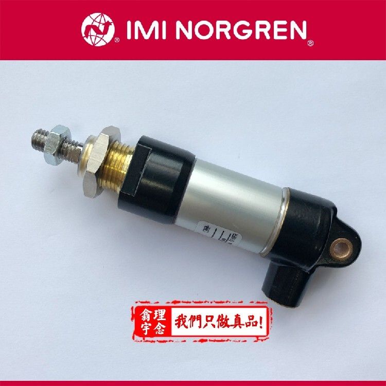
Micromagnetic valves are an integral part of industrial automation and precision control systems. However, these small and sophisticated components may experience congestion during their use, which not only affects the proper functioning of the equipment but may also adversely affect the system as a whole. This problem requires an in-depth understanding of its causes and measures to address it。
It is necessary to understand the causes of congestion, which may be caused by the accumulation of impurities, particles, sediments, etc., in the medium. In addition, chemical components in the medium may react to electromagnetic valve material, forming sediments and further causing congestion。
In order to prevent congestion, filters can be installed in front of the electromagnetic valve to reduce their likelihood of entering the electromagnetic valve by filtering impurities and particles in the medium. At the same time, regular inspections and cleaning of filters to ensure that they are working well are also important measures to prevent congestion。
When an electromagnetic valve is blocked, timely treatment measures are required. By changing the movement of the medium, this method washes the plugs out of the electromagnetic valve. If this method does not solve the problem, the electromagnetic valve will need to be removed for cleaning. In dismantling, we need to be careful not to damage parts and components of electromagnetic valves and to ensure that no new impurities are introduced into the cleaning process。
In addition to the above measures, the risk of electromagnetic valve congestion can be reduced by optimizing system design and media selection. For example, parameters such as flow speed, temperature, pressure, etc. Of the medium could be adjusted to make it more suitable for the use of electromagnetic valves. At the same time, the selection of electromagnetic valve materials that match the chemical properties of the medium is an effective means of preventing congestion。
The problem of congestion of micro-emagnetic valves is an issue that requires attention. By understanding the causes of congestion, taking precautions and dealing with congestion in a timely manner, we can ensure that the electromagnetic valves function properly and provide strong guarantees for the stable functioning of the system as a whole。