
Stable diode overview
The steady diode is also called the zina diode. Using pn contour reverse penetration, currents can vary in a wide range and the voltage is largely constant, resulting in a steady-pressure diode tube。
This diode is a semiconductor device that has high resistance until the critical reverse shock passes through the voltage. At this critical penetration point, reverse resistance is reduced to a very small value, with increased currents and constant voltage in this low resistance area, and the steady diode tube is segregated on the basis of piercing the voltage, as this characteristic is used primarily as a pressurer or as a baseline element of the voltage. The steady-pressure diode tube can be associated for use on higher voltage, and can obtain higher stable voltage by cascade。
Steady diode properties and working principles
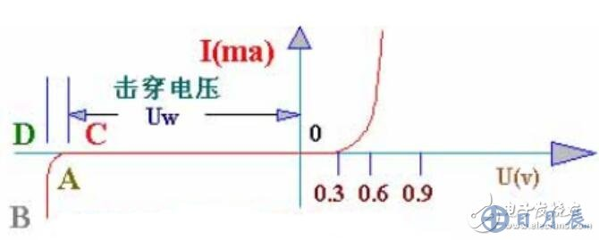
The steady-pressure diode is the type of diode that is commonly used in electronic circuits and is used to stabilize the voltage and works in reverse-firing. The positive properties of a steady diode are similar to those of a normal diode. Its reverse properties are that when the reverse voltage is lower than the reverse shock penetration, it is highly resistant and the reverse leak is minimal. However, when the reverse voltage approaches the threshold of reverse voltage, the reverse flow increases sharply, known as penetration, and the reverse resistance drops sharply to very small values at this critical thrust point。
Despite large-scale changes in currents, the voltage at both ends of the diode is largely stable near the piercing voltage, thus achieving a steady voltage function of the diode。
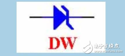
The two cw, two dw, and so on are the models of the steady pressure tube, and its circuit signs are graphic。
Volamic characterization curve of the steady pressure tube:
It's a stable diode
A simple smooth-pressure circuit consisting of a silicon steady-pressure tube. How does it work
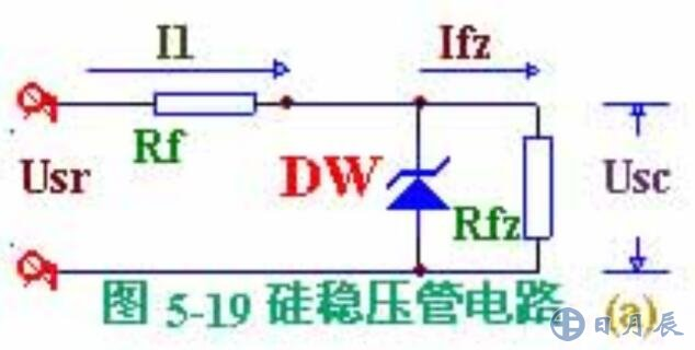
Analysis: if the grid voltage rises, so does the output voltage of the whole circuit, usr, causing the load voltage to rise. Since the steady-pressure dw is linked to the load of rfz, any small increase in the usc will result in a sharp increase in currents passing through the steady-pressure tube, which will also increase i1, and an increase in voltage on the restricted-control r1, thus offsetting the rise of usr and maintaining the load-pressure usc. On the other hand, if the grid voltage drops, causing usr to drop, and the usc to fall, then the currents in the steady tubes are drastically reduced, reducing i1 and the fall on r1, thus offsetting the fall in usr and keeping the load voltage of usc largely unchanged。
If usr does not change and load currents increase, the pressure drop on r1 increases, resulting in a drop in load voltage usc. Usc, with only a small drop, rapidly reduces the current in the steady voltage tube, which reduces the pressure down on the r1, thereby keeping the pressure down on the r1 largely unchanged and stabilizing the load voltage usc。
It was concluded that the steady-pressure tube functioned as an automatic regulation of currents, while the restricted-flow resistance functioned as an adjustment of voltage. The smaller the dynamic electrical resistance of the steady pressure tube, the greater the current resistance, the better the stability of the output voltage。
Steady-pressure diode identification method
1. Identification in circuits
A “zd” plus a number is commonly used in the circuit, e. G. Zd1 indicates a voltage tube numbered 1。
2. Positive and negative polar recognition
In terms of appearance, the metallic sealing of a steady-pressure diode tube is in a square and a negative pole in a semi-circle. The plastic-constricted diode tube is marked with a negative polar at one end and a positive polar at the other end. The polarity of a stable diode, which is not clearly marked, can also be distinguished by a universal scale, measured in the same way as the normal diode。
3-cyclical palsy diode recognition
The chromatic ring on the cylindrical voltage represents two meanings: the first is the number and the second is the decimal number (normally, the cytological voltage of the cylindrical voltage is one decimal, expressed in brown. It can also be understood as a multiplier, i. E. X10 (one side), with the exact colour corresponding to the number of cyclops。
4. Distinction from the general swath diode
First, a positive and negative electrodes of the tube are judged using a universal rx1k block. It is then assigned to the rx10k block, the black pen is connected to the negative pole of the tube, the red pen is connected to the positive pole of the tube, and if the measured reverse electrical resistance is much smaller than the reverse resistance measured in the rx1k block, it is shown to be a steady pressure tube; conversely, if the measured reverse electrical resistance is still large, the tube is a whole-stream diode or a wave diode。
Four steady-pressure diode applications
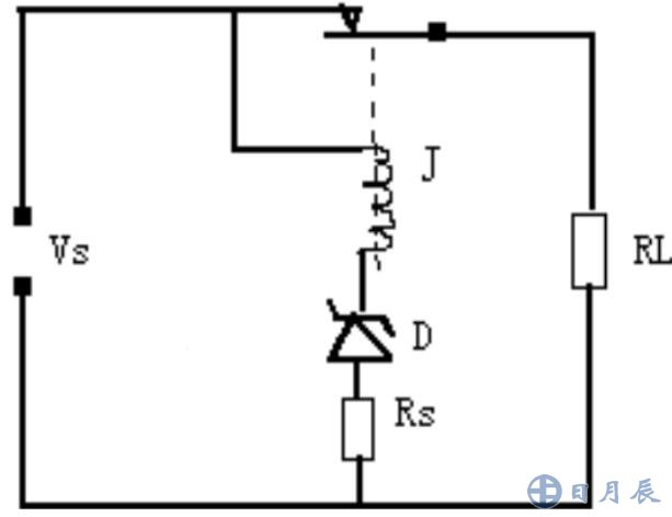
A steady pressure tube is punctured by an accurate voltage, which allows it to be used as a restriction or protective element, as the voltage of the voltage is available and is therefore particularly appropriate for this application. The steady pressure diode d in the figure is used as an overpressure protection. As long as the power voltage vs exceeds the stable voltage value of the diode tube d, the relay j absorbs load rl and the power is separated。
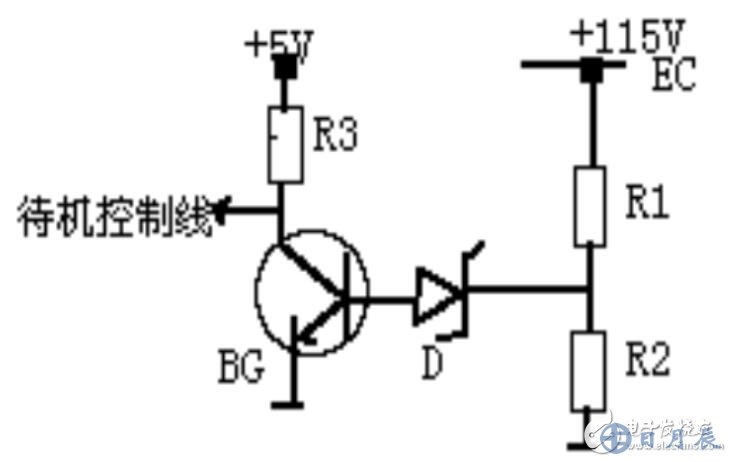
2. Overpressure protection circuits on tv
Ec is the main electric voltage of the television, when the voltage of the ec is too high, the d-conductor, the tripolar bg-conductor, whose assembly pole level will be converted from the original high level (5v) to low level, and the television will be placed on standby through the control of the standby control line。
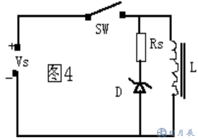
3. Arc suppression circuits
As shown in the figure: when the wire is cut, the high pressure generated by its electromagnetic release is absorbed by the diode, when the switch is broken, the arc of the switch is removed. This applied circuit is more used in industry, such as some of the more powerful electromagnetic suck control circuits。
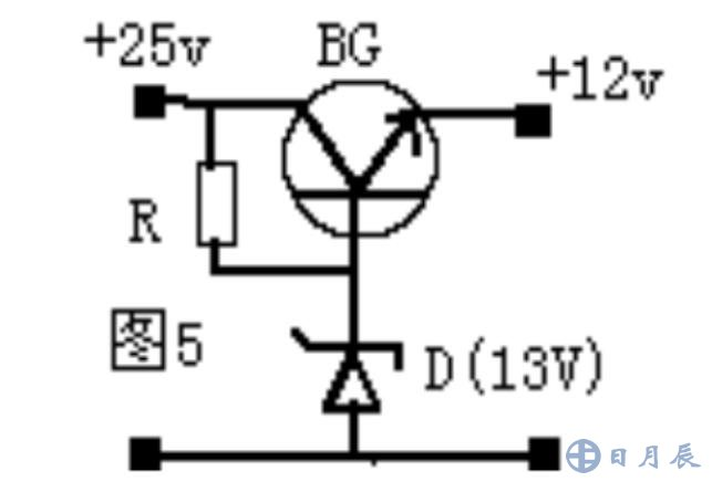
4. A series of steady voltage circuits
The circuit, as shown by the chart, in this circuit, a chain of compressor tubes, the base pole of the bg, which is set at 13v by a steady diode d, is capable of producing a constant 12v voltage. This circuit is used on many occasions。
• previous article: the strangeness of the study made organic diode lasers a reality


