
Steady diodes. Steady diodes, steady circuits
Steady diodes. Steady diodes, steady circuits
An understanding of the working principles of the steady diode would be sufficient to understand the reverse properties of the diode。
All transistor diodes, the basic characteristic of which is one-way guidance. That is to say, it's leading to pressure. It's not working. One condition here is that reverse pressurization does not exceed the reverse stress of the tube。
What's the result of exceeding the stress tolerance
Answer 1: pipes burned。
The test found that, as long as the reverse current value (e. G. A chain of resistance between the tube and the power source) was restricted, the tube would not be burned, although it was punctured。
Moreover, when the tube is punched backwards, the current changes from large to small, and the voltage drops only marginally, and it drops sharply with a certain current value. It's this characteristic that makes a steady diode. The key to using a steady-pressure diode is to design its current value。
The steady pressure of the diodes is characterized by penetration, with essentially constant voltage at both ends. Thus, when a steady voltage tube is connected to the circuit, the voltage at both ends of the load will remain essentially the same if the voltage of the power source fluctuates or if the voltage at each point of the circuit is altered for other reasons。
I. Equipment and equipment
In general, the tripolar tube is a positive guide, with a reverse cut-off; plus reverse voltage on the diode, which, if it is beyond the capacity of the diode, will be punctured and destroyed. But there's a diode, which has the same positive properties as a normal diode, whereas the reverse properties are special:
When the reverse voltage is added to a certain degree, the tubes, though penetrating, are not destroyed by larger currents, and the repetition of this phenomenon is good; in turn, as long as the tube is in a piercing state, although the electricity flowing through the tube is very different, the voltage at both ends of the tube is very small and has a steady effect. This special diode is called the pressure tube。
The models of the pressure-control tube are 2 cw, 2 dw, etc., and its circuit signs are shown in figures 5-17。
The pressure-pressure properties of the steady tube can be clearly expressed in the voltage properties curve shown in figure 518。
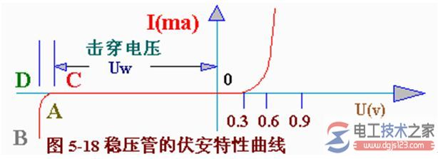
The pressure-control tube is operated using the steady pressure properties of the reverse strike multiple zones, so that the pressure-control tube is connected in reverse in the circuit. The voltage of the smoother tube is described as stable voltage, and the stable voltage of the different types of voltage tube is different, and the stable voltage of a particular type of voltage tube is fixed to an oral range. For example, 2cw11 has a steady pressure of 3. 2 to 4. 5 volts, one of which may be 3. 5 volts and the other of which may be 4,2 volts。
In practical applications, if a pressure tube that does not match the required pressure value is selected, a pressure tube with a lower pressure value may be selected, followed by a combination of one or more silicon diode “plough pads” to raise the stable voltage to the required value. This is based on the positive pressure down to 0. 6 to 0. 7 volts of silicon diodes. Thus, the diodes must have a direct connection in the circuit, which is different from the compressor。
The quality of the pressure steadyness of the pressure tube can be expressed in terms of its dynamic resistancer:
It is clear that for the same current variability, the smaller the voltage change at both ends of the compressor, the smaller the dynamic resistance, the better the compressor performance。
Dynamic electrical resistance in a steady pressure tube changes with the current at work, which increases. The smaller the dynamic electrical resistance. Therefore, in order for the pressure to work well, the work current must be selected. Work currents are larger and can reduce dynamic resistance, but cannot exceed the maximum allowable current (or maximum deplete power) of the tube. Working currents and maximum allowable currents for various models can be found in the manual。
The stability of the pressure tube is subject to temperature changes, and when the temperature changes, its stable voltage is subject to change. The temperature coefficients of the stable voltage are commonly used to indicate this performance, e. G. The stable voltage uw = 12 volts for the 2cw19 steady voltage tube, with a temperature factor of 0. 095 °c, indicating that the stable voltage increases 11. 4 mv for each temperature increase. In order to improve the stability of circuits, appropriate temperature compensation measures are often used. In cases where stability can be highly demanding, a steady pressure with a temperature compensation is required, such as 2dw7a, 2dw7w, 2dw7c, etc。
Ii. Map of steady voltage of the diodes
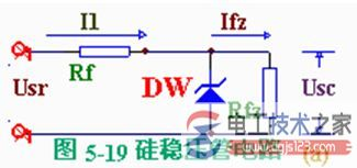
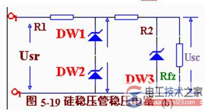
A simple, steady voltage circuit consisting of a silicon piping tube is shown in figure 5-l9(a). Silicon steady-pressure dw and load rfz, combined with r1 limited current resistance。
How does this circuit work?
If the grid voltage rises, so does the output voltage of the whole circuit, which causes the load voltage to rise. As the steady-pressure dw is linked to the load of rfz, a slight increase in the usc would result in a sharp increase in currents passing through the steady-pressure tube, which would increase i1, and a decrease in voltage on the restricted-control r1, thus offsetting the rise of usr and keeping the load-pressure of usc largely unchanged. Conversely, if grid voltage is reduced, causing usr to fall and usc to fall, the current in the steady pipe is drastically reduced, reducing i1 and r1, thus offsetting the fall in usr and keeping the load voltage of usc largely unchanged。
If usr does not change and load currents increase, the pressure drop on r1 increases, resulting in a drop in load voltage usc. With only a small drop, the current in the steady pressure tube is rapidly reduced, reducing the pressure down on the r1 and thus keeping the pressure down on the r1 largely unchanged, thereby stabilizing the load voltage usc。
In summary, the smoother tubes function as automatic current regulation, while the limited-flow resistance function as voltage adjustment. The smaller the dynamic electrical resistance of the steady pressure tube, the greater the current resistance, the better the stability of the output voltage。


