The lock phase is an automatic control of phase synchronization, and an automated control closed loop system capable of completing the synchronization of two telecommunications phases is called the lock link, or pll. It is widely applied in such technical areas as broadcast communications, frequency synthesis, automatic control of timely bell synchronization, etc。
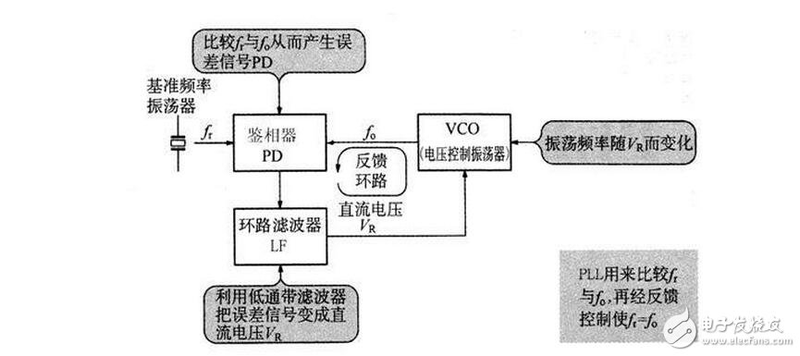
A typical lock-ring (pll) system consists of three basic circuits, such as graphics, of forensics (pd), voltage control (vco) and lpf
620)this. Width=620; "syle=cursor:point"/
The capture and tracking of the chain circuit
When the chain cycle is starting to work, it is generally unlocked at the start, and because there is a phase difference between the two-way signals entered into the catheter, the catheter changes the oscillation frequency of the pressure-controlled oscillator by the output error voltage to match the reference signal. The chaining process is from missing to locked, which is known as the capture process. The maximum frequency range or maximum inherent frequency band that the system can capture is called catch band or catch band。
When the chain loop is locked, for some reason changes in the frequency of the input signal or pressure-controlled oscillator can be quickly adjusted through its own feedback. The result was that vco output frequency and phase were locked in the base signal parameters, thus maintaining the lock on the ring path. This process is known as the tracking of the ring road. The system maintains the maximum frequency range or the maximum inherent frequency band for tracking, referred to as synchronous band or synchronous range, or lock range。
The capture and tracking processes are two different automated processes for locking the loop。
As a result, there are fixed frequency differentials in the afr circuits that are locked. A fixed phase difference occurs when the chain is locked. Although there is a phase differential in the chain ring, there is no frequency difference between it and the base signal, i. E. The output frequency equals the input frequency. It also shows that frequency control is done by locking the trajectories, so it's possible to track the exact difference. The effect is far better than automatic frequency control of circuits。
I. Separators (pd)
Separators are a key unit circuit in the chain circuit that compares the two-way input signals and sends the results out of the output end. The types of circuits are numerous, with the following three most commonly used。
(1) simulation multiplication separators separators, which are often used for both-way input signals of the separators, are in the lock-ring circuits of the sine wave。
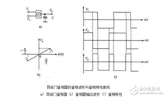
(2) an alien or door separators, which are suitable for a lock-ring circuit in which the two-way input signal is a square wave signal, are often used in a digital circuit lock-ring circuit。
(3) border-trigger digital spectrometers, which are also digital circuit spectrometers, are not subject to stringent requirements for input signals, either square waves or rectangular pulses, which are often used in high frequency digital chain circuits。
620)this. Width=620; "syle=cursor:point"/
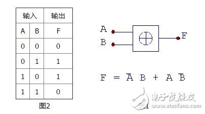
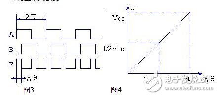
1. The logical true value of the different or separators or the door is shown in table 1, and figure 2 is a logical symbol。
620)this. Width=620; "syle=cursor:point"/
As can be seen from table 1, if end-end a and b send a signal waveform with a 50 per cent space ratio, respectively, the wave-form ratio of the output-f is related to the wave-form of the logarithm, as shown in figure 3. If the f output wave shape is smoothed through the scorer, then the factoror output mean of the waveform, which is also associated with the luminum, can be used to convert the phase to the voltage and form the phase checkout circuit. So the average after the crediter points is:
U = vdd
Different gills, different straight-flow vds. The relationship with v can be described in figure 4. As can be seen from the figure, the two are in a simple linear relationship:
Ud = kd * (2)
Kd is sensitive
620)this. Width=620; "syle=cursor:point"/
2. As previously mentioned, the different or door phase compressor must, when used, require two contrasting signals to be in a waveform of 50% of the space ratio, which creates some inconvenience for the application. The frame triggers the signature by comparing the up-to-up (or down-by-the-side) line of the two input signals, with no requirement for the space ratio of the input signal。
Ii. Pressure oscillator (vco)
The voltage oscillator is the oscillator with a oscillation frequency ω under control voltage uf(t), i. E. A voltage-frequency converter. The properties of the vco can be expressed by the relationship curve between the instant frequency ω0(t) and the controlled voltage uf(t). In the absence of control of the voltage (but it cannot be assumed that control of the direct current voltage is 0, since the controlled end voltage should be the sum of the direct current voltage and control of the voltage), the oscillation frequency of the vco, known as the free oscillation frequency ωom, or the central frequency, within the linear control of the vco, the instant angle frequency may be expressed as:
ω(t)=ωom + k0 uf(t)
In formula, the slope of the k0-vco control characteristic curve is commonly referred to as the control sensitivity of the vco or the pressure control sensitivity。
The pressure oscillator (vco) is the subject of a chain link (pll). Pressure-controlled oscillator is a voltage-frequency converter, which is used as a frequency-modifiable oscillator in the ring and the frequency of the oscillation shall change in a linear manner with the input control. Its output signals can be divided into two categories according to the different requirements of the chain cycle: the sine wave pressure oscillator and the non-sine wave pressure oscillator。
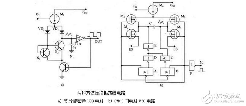
Sinewave pressure oscillator typically consists of a lc point oscillator and a modified diode. It works in exactly the same way as the formula and the three-point sine wave oscillator. Since the sine wave vco is limited by the range of transformational diode condensation capacitation, the range of general oscillation frequency variations is not significant. The arctic wave-pressure oscillator is more widely used because of its large frequency range and good linearity. Several of the circuits common to these voltage oscillators are radio-ticking time pressure-control polyphonic oscillators, spectro-smitt pressure oscillators, and digital door circuit voltage oscillators。
This is illustrated by the circuits of the oscillator at two square wave pressure。
620)this. Width=620; "syle=cursor:point"/
Iii. Ring filters
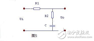
This is only about passive fraction filters, as shown in figure 5. Its conveyor function is:
620)this. Width=620; "syle=cursor:point"/
Where: 1 = r1 c
And 2 = r2 c
620)this. Width=620; "syle=cursor:point"/
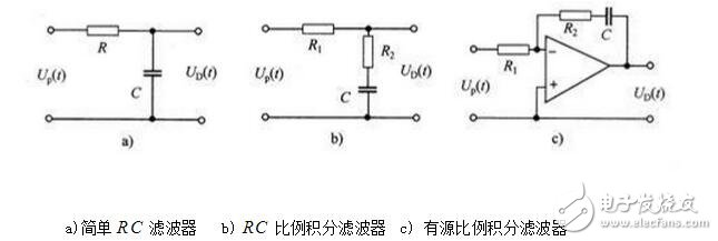
The figure is the three circuit filter circuits that are currently more common. The graph shows that the complexity of the three circuits varies. The first simple rc filter uses the least element and the simplest circuit. There's a ratio filter that uses the most components, and the circuits are complicated。
620)this. Width=620; "syle=cursor:point"/
However, in terms of the filter effect, the filter effect of the active ratio filter is best, the filter effect of the simple rc filter is the least, and the filter effect of the rc scale filter is in between. When designing circuits, different loop filters can be selected according to the requirements of the chain circuit。
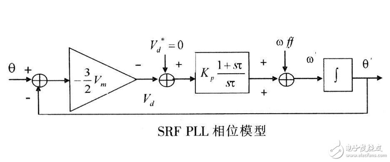
Iv. Phase model and transmission function of the chain ring
620)this. Width=620; "syle=cursor:point"/
Figure is a chained phase model. Note that the chain is a phase feedback system that circulates in a phase rather than a voltage. Thus, the study of the chained phase model allows for the integrity of the loop。
As can be seen from figure 6:
(1) when point a breaks the loop, the open-ring phase transfer function of the chain link is:
620)this. Width=620; "syle=cursor:point"/
(2) the phase transfer function when the ring is closed is
620)this. Width=620; "syle=cursor:point"/
(3) the phase error transfer function when the ring is closed is
620)this. Width=620; "syle=cursor:point"/
When the loop filter selects the passive proportional fraction filter, it is derived that:
620)this. Width=620; "syle=cursor:point"/
Where
620)this. Width=620; "syle=cursor:point"/
620)this. Width=620; "syle=cursor:point"/
620)this. Width=620; "syle=cursor:point"/
The same applies to:
620)this. Width=620; "syle=cursor:point"/
ωn is referred to as the inherent frequency or natural angular frequency of the system
X referred to as the system's resistance coefficient。
Note that, in the above discussion, the luminum refers to the frequency of the input of the angle of the signal phase, not the frequency of the input of the signal itself. If the input signal is an fm signal, the zirconium refers to the angular frequency of the moded signal rather than the angular frequency of the carrier。
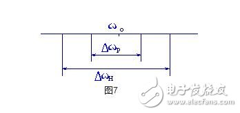
V. Synchronization and capture of chains
The output frequency (or vco frequency) ωo of the chain link tracks the working state of the input frequency ωi, known as the synchronized state, which always has ωo = ωi. Enter the maximum variation range of the frequency ωi, known as the synchronous bandwidth, expressed in dωh, under the condition that the chain is kept synchronized. Beyond that, the ring is locked。
When the lock is missing, the ωi, if it attempts to change the ωi from both directions to the ωo, then the =o = (ωi-ω) ↓, and when the Δωo is small to a certain value, the loop goes from missing to locked. This frequency range, which leads to the locking of pll through the frequency pull, is called the catch belt p. Synchronizes the relationship between the gill h, catch the gillp and the vco central frequency ωo as figure 7。
620)this. Width=620; "syle=cursor:point"/