


This is a generic pivot that we share today, and we believe that most of our friends are using, applying, representative, and fundamental, the role of the piping. Of course, specific projects and venues may encounter different situations, so it is not certain that this will be strictly applied. The broad principles are in place. It is always appropriate to be flexible, tailor-made and tailor-made special measures, and new experiences are essential to solve the problem. It is always the best way to implement a more realistic approach to their own projects. Watch and share. Welcome to the collection
I. Comprehensive guidelines
General principles
1. 1 primacy of the tube, with the small tube allowing the tube
1. 2 pressure-free tubes
1. 3 low pressure tubes to avoid high pressure tubes
1. 4 hot, cryogenic tubes
1. 5 curved lines allow non-curved lines, branch lines, and main lines
1. 6 low-annex pipelines avoid multiple-annex pipe lines and install, repair and repair space 500 mm
1. 7 electrical pipelines for hot water avoidance, which are not suitable for electrical lines at the vertical lower end of the hot line, above the vapour line and below the water pipe
1. 8 when there is no large overlap between specialized pipelines (e. G. Garages): water pipes and bridges are placed in the upper layer and wind pipes in the lower layer; if there is also a gravity pipe, wind pipes are placed in the upper layer and pipes and bridges are placed in the lower layer
1. 9 when there is a wide overlap between specialized pipes (e. G., walkways, core drums, etc.), the order of each specialized pipe is set from the top to the bottom: ventilation without the need to open a vent, ventilation with the need to open a vent, bridge frames, water pipes
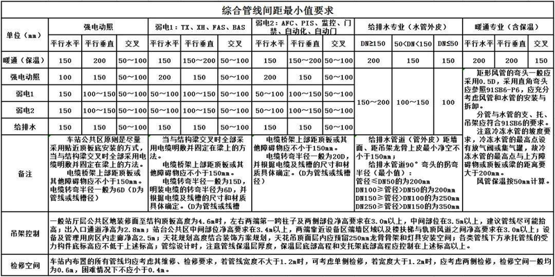
1. 10 the minimum spacing of integrated tube lines requires:
2. Structural specialization
2. 1 areas already marked on the structural plane as refilling plates, which are not otherwise indicated if holes are left in such areas
2. 2 in the structural plane, a hole of less than 300 x 300 in general does not mean otherwise
2. 3 the placement of holes in the top plate of the human protected area, regardless of the size of the hole, requires a professional structural confirmation and is shown on the chart
2. 4 if beams are required for the equipment pipeline, the opening dimension shall be less than 1/3 beam height and less than 250. The opening position is at the centre of the beam height. On the plane, one third of the beam is located. The beam positioning needs to be professionally structured and presented on the chart at the same time
2. 5 in the case of holes in the shear wall, a hole of less than 300 x 300 is generally not indicated. However, the equipment is specialized in hole-keeping, and attention is required to remain at the centre of the wall and not to approach the wall or the corner, avoiding contact with the dark column. When a hole is left on the wall at the scene, if the hole is found to touch a pillar, the structural profession is notified for processing
2. 6 when piercing a beam, the opening dimension shall be less than 1/3 beam height and less than 800
2. 7 small, dissatisfied holes, where other professions must be clear and confirmed before construction can take place
2. 8 structured floors with no piercing of the cap range。
3. Water
3. 1 pipelines shall have as few bends as possible
3. 2 water lines are on top and drainage lines on the bottom. (a) the temperature piping is on top, the temperature piping is on the floor, and the small caliber piping should, as far as possible, be supported by a large caliber piping road or hanging under the piping road
3. 3 non-pressure-free pipes with slopes shall never be able to rise, except for those designed to lift pumps
3. 4 the net distance between the introduction of water and the discharge tube shall not be less than 1 m. The minimum net spacing between the two tubes shall not be less than 0. 2 m when the indoor water supply and drainage pipes are installed in parallel; and the vertical net spacing shall not be less than 0. 15 m when cross-laying. (b) water pipes should be laid above the drainage pipes, and if they must be laid below the drainage pipes, pipes should be fitted with pipes that are not less than three times the length of the drain
3. 5 the spacing between the stairwells shall be no less than 100 mm from the stairwells
3. 6 natural drainage lines, such as sewage, rain drains and wastewater drainage, shall not be rolled up and other pipes shall avoid gravity lines
3. 7 there shall be sufficient space on the upper or horizontal configuration of the water pipeline
3. 8 water pipes shall be placed below the bridge shelf when they are stacked
3. 9 pipelines shall not block doors or windows and shall avoid being passed above the electrode plate, distribution plate and dashboard
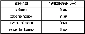
3. 10 the minimum distance between the outer walls of the pipe shall not be less than 100 mm, the piping valve shall not be installed in parallel rows, shall be staggered, and the net distance shall not be less than 200 mm if installed in parallel columns
3. 11 take note of the condensed drainage pipes with a condensed surface thickness of 25 mm
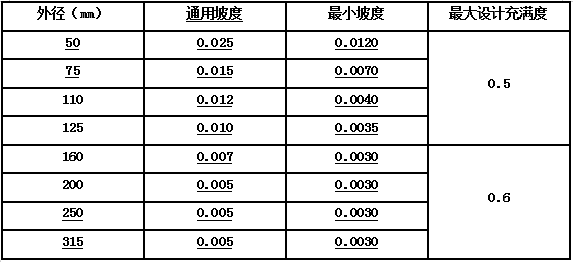
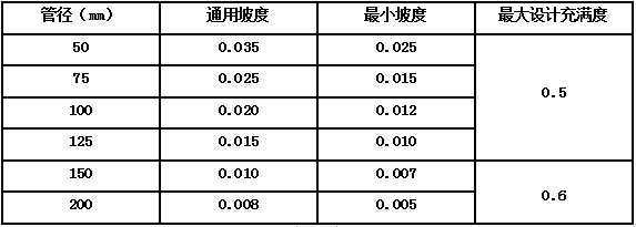
3. 12 slope control forms for drainage pipes:
4 heating professional
4. 1 gravity slopes shall be guaranteed for pressureless tubes (air conditioners specializing only in condensing pipes) and, to the extent possible, shall avoid crossing and superheavying of the pressureless tubes with other pipes to control the upper layers
4. 2 for the most prominent part of the pipeline, such as the outer wall of the pipe, the edge of the franc and the outer wall of the thermal insulation layer, the net distance from the wall or column shall be 100 mm
4. 3 in the event of a lack of space, communication with the designer is possible, with a smaller profile to facilitate higher markings
4. 4 refrigerated condensed water shall take into account the slope, the actual installation of the ceiling shall normally be determined by the minimum point of condensed water, the condensed pipe shall be no less than 0. 01 per cent from the winder pipe to the horizontal dry pipe and the cooled condensed pipe shall be not less than 0. 008 per cent of the lower slope in the direction of drainage
4. 5 air-conditioning refrigerated water pipes, ethanol tubes, air-conditioning wind pipes and flue pipes within the ceilings are subject to temperature protection and the width of the wind pipes is generally considered at 35 mm。
5 electrical
5. 1 cable slots and bridge frames shall be above the surface of 2. 2 m. (b) it is not appropriate to have less than 0. 3 m at the top of the trough and bridge or other barrier
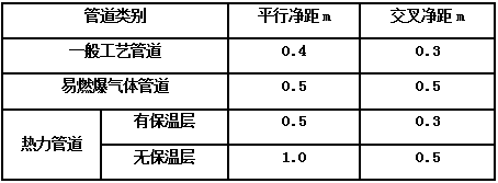
5. 2 cable bridge frames shall be placed below the flammable, explosive gas tubes and heat pipes and, when not designed, the minimum net distance from the pipeline shall meet the following requirements:
5. 3 the opening surface of the cap shall be kept 80 mm vertically clean, preferably at a distance of 100 mm from other professions, at the inside of the ceiling
5. 4 a net distance of not less than 0. 5 m at the time of the communication of the cable bridge and the electrical equipment used
5. 5 when two sets of cable bridges are mounted in parallel at the same height at a distance of not less than 0. 6 m, and when the object side of the bridge is not less than 0. 6 m at a level of distance along the wall, windpipe, etc. (the columns below 1 m in part may not be affected), the parallel spacing of the two sets of cables may be treated at not less than 0. 2 m. (b) 100 mm net distance from the wall or pole
5. 6 the curved radius on the inner side of the cable bridge shall not be less than 0. 3 m
5. 7 when a cable bridge is installed in multiple layers, the control bridge is not less than 0. 15 m, the electrical cable is not less than 0. 25 m, and when the cable bridge is not less than 30° interlocking, the distance may be reduced by an appropriate amount of 0. 1 m, not less than 0. 5 m between a weak electrical cable and a electrical cable, not less than 0. 3 m if a shield is in place, and not less than 0. 3 m if the upper roof of the bridge or any other barrier
5. 8 cable bridge frames shall not be fitted to the upper and lower of the corrosive gas and heat pipes
5. 9 communications bridge is at least 300 mm horizontal distance from the other bridge and 300 mm vertically to prevent interference from the other bridge magnetic field
5. 10 the ramp is to be slowed down when the bridge shelf is up and down, with a distance of 100 mm in parallel with the other pipes; and 5. 11 the bridge shelf is not fit to wear a stairwell, air-conditioning room, pipe well, wind well, etc., and when encountered, to make the best possible bypass
5. 12 strong bridge frames shall be installed close to the distribution room and, if mounted on or off the bridge, preference shall be given to strong bridge frames above
5. 13 when a high-pressure low-pressure bridge is installed, the high-pressure bridge shall be placed above the low-pressure bridge shelf at a distance not less than 0. 5 m
5. 14 not less than 10 mm between weak cells
5. 15 no less than 300 mm between weak cells and strong bridges
5. 16 when strong power is used in a surface metal cell, the distance between a weak and a strong cell is not less than 150 mm。
Ii. Bim delivery
1 requirements for modelling prior to line integration
1. 1 construction professional modelling: requires accurate positioning of stairwells, elevators, tube wells, stairwells, electrical distributions, air conditioners, pumping rooms, changing the size of the plumbing of the heat station, ceiling height, etc.
1. 2 structure professional modelling: requires that beams, plates, columns beams beams beams and columns beams beams beams beams beams and position sizes beams beams beams; the interior beams need to be high enough to conform to the design requirements, such as the need for the designer to give a detailed graft map of the beams in contact with the tube beams, and bim to make the nodal of the beams beams beams
1. 3 water professional modelling requirements: the names of the systems must be consistent with the drawings; some water pipes that require additional slopes must be graded according to the drawings; valves in the system must be added to the positions in the drawings; and pipes with a conservatory layer must be built up
1. 4 professional modelling requirements for heating: require systems to be named in a manner consistent with drawings; some equipment, end end-of-pipes that affect the integration of pipes to be constructed according to drawing requirements, e. G., windpipes, vents, etc.; heating water system modelling requirements to be consistent with water professional modelling requirements; and insulation lines to be constructed
1. 5 electrical professions: systems are required to have the same name as drawings。
2. Attention during pipeline integration
2. 1 identification of the substrate height of the beams and the height of the hoists in each position within the ceiling space
2. 2 examination of the lack of models in the various professions and understanding of the complex location of the pipes
2. 3 high base wind pipes and high plumbing centres as required by the design
2. 4 distribution of their respective positions within the ceiling space as required by the respective professions. (b) general construction, from top to bottom, specialized in heating, electrical, water
2. 5 the route of the drawings in the model needs to be changed, and please coordinate with the designer. The heating and ventilation profession encounters particularly compact pipes, but in order to ensure the height of the ceiling, it should be coordinated with the designers when changing the size of the section。


