The concept of “place” and “access”
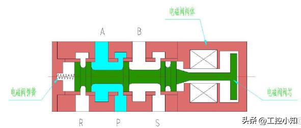
The two three-wire electromagnetic valves consist of electromagnetic wires and cores and are valves with three holes. When it receives electricity from its coil or it loses it, the core moves to make the flow pass the valve or block it for the purpose of changing the direction of the gas source。
"bit" means that the electromagnetic drive cores that are generated by electromagnetic wires when electrocuted are in different positions, with different routes. Several of the core locations are called electromagnetic valves。
“across” refers to the number of interfaces on the emp valve, i. E. The number of routes through which several gateways are referred to as several electromagnetic valves。
Ii. Rationale
In the start-up circuit, the function of the electromagnetic valve control switch valve is to control the flow of the gas flow channel, and the break-off changes the direction of the compressed air, mainly by using the electromagnetic force generated by the electromagnetic loop to drive the core switch and achieve the flow switch。
The thrust of the switch valves according to the electromagnetic control component may be divided into direct and lead electromagnetic valves。
Electromagnetic valves are divided into single and double power controls according to the power source, with voltage divided into 220 v, 110 v and 24 v; they can also be divided into blast and non-explosive。
The interfaces of the electromagnetic valve gas route are 1/4 inch, 1/2 inch, 3/8 inch, etc。
2. 1 electromagnetic valve function
In electrical control, electromagnetic valves are capable of performing functions such as direction control of the action of the gas-activated component, control of the o/off switch, or or/not/and logical control。
Electromagnetic valves control the passage or change the direction of the compressed air in the gas movement circuit。
The electromagnetic valves are only an attachment to the aerodynamic control valves and control the gas source routes of the aerodynamic valves。
Electromagnetic valves are also commonly used to control the break-off of gas source circuits through voltage signals to control valve switches。
The electromagnetic valves have a larger circulation calibre than the locator and can sometimes be used for valves that require rapid opening and closure。
A single electro-controlled electromagnetic valve has a failure or frequent position and can be used for gas breakup protection。
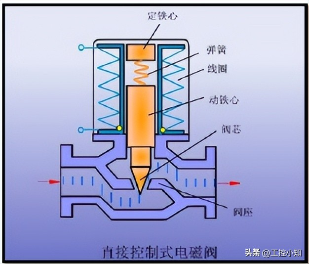
2. 2 activation of direct electromagnetic valves
When electro-magnetic force is used to drive the core of the valve to switch, the valve opens the fluid through, the valve closes and the fluid cannot pass when it loses power。
2. 3 guided emp working principles
The conductive electromagnetic valves are activated by electromagnetic forces to open the lead valves, to bring the gases into the em valve core gas chamber, to use the pressure to boost the em valve core and to achieve a break between the airways。
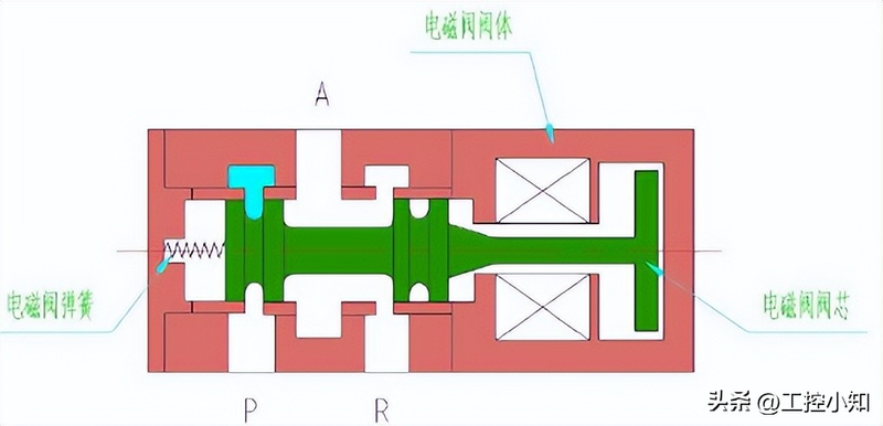
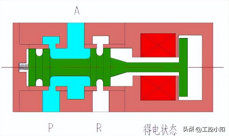
2. 4 single-electrical direct motion 2d 3-channel electromagnetic valves
The electromagnetic valve core has two locations and three airway interfaces. As shown in the figure below, p is the gas source interface, a is the access to the aerodynamic implementer interface and r is the vent。
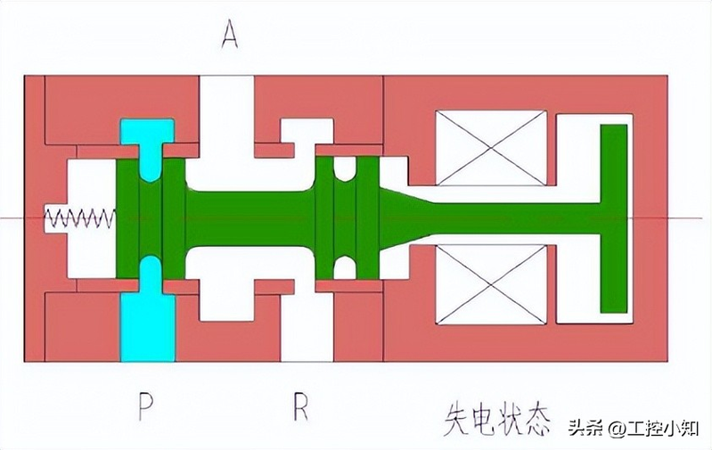
Initial state (power failure): as shown in the figure below, the electromagnetic valve is out of power at this time, the core of the valve is on the right side, the a is connected to the r, the cylinder is exhausting and the p is closed。
(c) working status (electricity): as shown in the figure below, the electromagnetic valve is electro-powered, its core is sucked to the left by electromagnetic force, the p mouth is connected to mouth a, the gas source is from mouth a to tank r is closed。
If the power is lost, the valve core returns to the initial state of the failure with the spring。
2. 5 single-electric direct motion 2d five electromagnetic valves
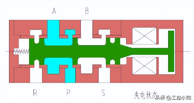
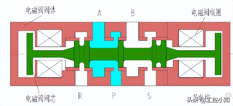
The electromagnetic valve core has two locations and five airway interfaces, as shown in the figure below, with the p mouth being the air source interface, the a and b being the access to the aerodynamic implementer interface and the r and s being the vent。
Initial state (out of electricity): as shown in the figure below, the electromagnetic valve is out of power at this time, the core of the valve is on the right side, the p mouth is connected to a, the gas source is through a to the gas chamber on the side of the cylinder, the b is connected to s, the other side of the cylinder with b is out of air and the r is closed。
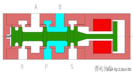
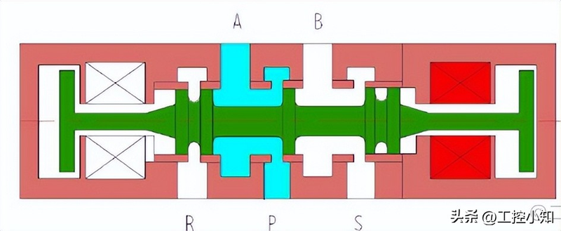
Working state (electricity): as shown in the figure below, the electromagnetic valve is electrostatic at this time, the core of the valve is sucked to the left with the effect of the electromagnetic force, the p and b are connected, the gas source enters the gas chamber on the other side of the cylinder through b, the a and r are connected, the vent is ventilated on the side of the cylinder with a and the s is closed。
If the power is lost, the valve core returns to its initial state with the spring。
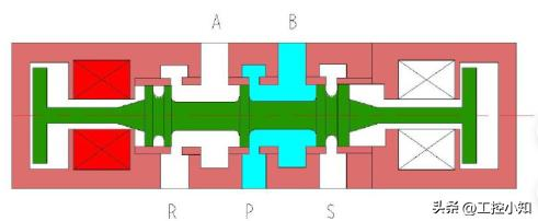
2. 6 two-power-controlled direct motion two-digit five-power electromagnetic valves
Initial state: at this time the electromagnetic valve is free of electricity, the core of the valve is on any side to the right (this figure is on the right side), the p is connected to the a, the gas is channelled through a to the gas chamber on the side of the tank, the b is connected to the s, the side of the cylinder is in an exhaust state with b and the r is closed。
On the right side of the electrocution state: as shown in the figure below, the right side of the electromagnetic valve is powered at this time, the core of the valve is sucked to the right side, the p mouth is connected to a, the gas is channelled through a to the gas chamber on the side of the cylinder, the b is connected to s, the side of the cylinder is exhaustive and the r is closed. Two electro-controlled electromagnetic valves have memory functions, i. E., at this point the right wire is out of power and the em valve core remains intact on the right when the left is out of power。
On the left side of the electrocution state: as shown in the figure below, the left side of the electromagnetic valve is charged at this time, the core of the valve is sucked to the left, the p mouth is connected to b, the gas source is passed through b into the gas chamber on the side of the cylinder, the a is connected to r, the side of the cylinder with a is ventilated and the s mouth is closed. Two electro-controlled electromagnetic valves have memory functions, i. E., the core of the electromagnetic valve remains intact on the left side of the line at this time, when the right side of the line is unelectric。
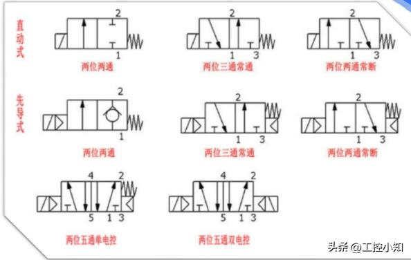
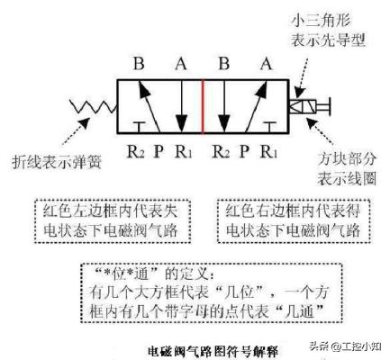
Iii. Meaning of a graphic symbol for an electromagnetic valve
The working position of the valve is shown in boxes, each indicating a working position of the electromagnetic valve, or "bit " , with several boxes indicating " bits " , such as two three-channel electromagnetic valves indicating two working positions。
The arrow in the box indicates that the airway is connected, but the arrow direction does not necessarily indicate the actual direction of the fluid。
Box
This means the road is out。
The number of interfaces that are connected to the outside of the box is several, which means a few “passed”。
In general, valves are shown in the letter p for vents connected to the system airway; valves are shown in r (sometimes in t); and valves are shown in a, b, etc. For vents connected to the execution element。
Each of the electromagnetic valves has two or more working positions, one of which is a normal position, i. E. Where the core is not manipulated. The two valves that use spring repositioning are the normal position of the route in the box near the spring. When drawing the system map, the airways shall normally be connected to the normal position of the switch valve。
3. 1 electromagnetic valve air route symbols
3. 2 two three-ton electromagnetic valve symbols
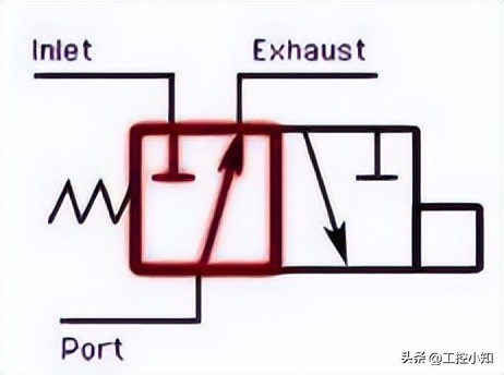
Two three-wire electromagnetic valves are two positions of three vents, one of which is the vent (p) and the other two are the vent (a/b), and when the electromagnetic valves receive electricity, p and a, p and b when the power is out。
3. 3 common electromagnetic valve symbols