
Overview
The cooling fluids damage the paint surface. If the cooling fluid spills, the cooling fluid is quickly wiped out and washed with clean water。
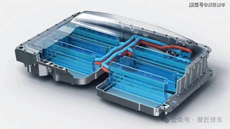
The cooling system uses the principles of thermal conductivity to allow peu f (former reverser), peu r (reverse reverser), drivers, high-pressure direct-flow transformation integrated components and high-voltage batteries to remain at the optimal working temperature, with temperature values varying from -40°c ~100°c depending on the condition of the work and the temperature of the environment。
Refrigerated fluids need to be replaced periodically (specifically checking replacement requirements are referred to in the vehicle maintenance section of the user manual) in order to maintain their optimal efficiency and corrosivity. Different combinations of inhibitors may lead to reduced protection against corrosion。
Annotations
The front-end cooling module is the smart expansion of the kettle cooling pipe
Smart swelling kettle
Spills of steam or cooling fluids can cause injuries such as burns, so when the cooling system is still hot, do not open the swelling kettle cap。
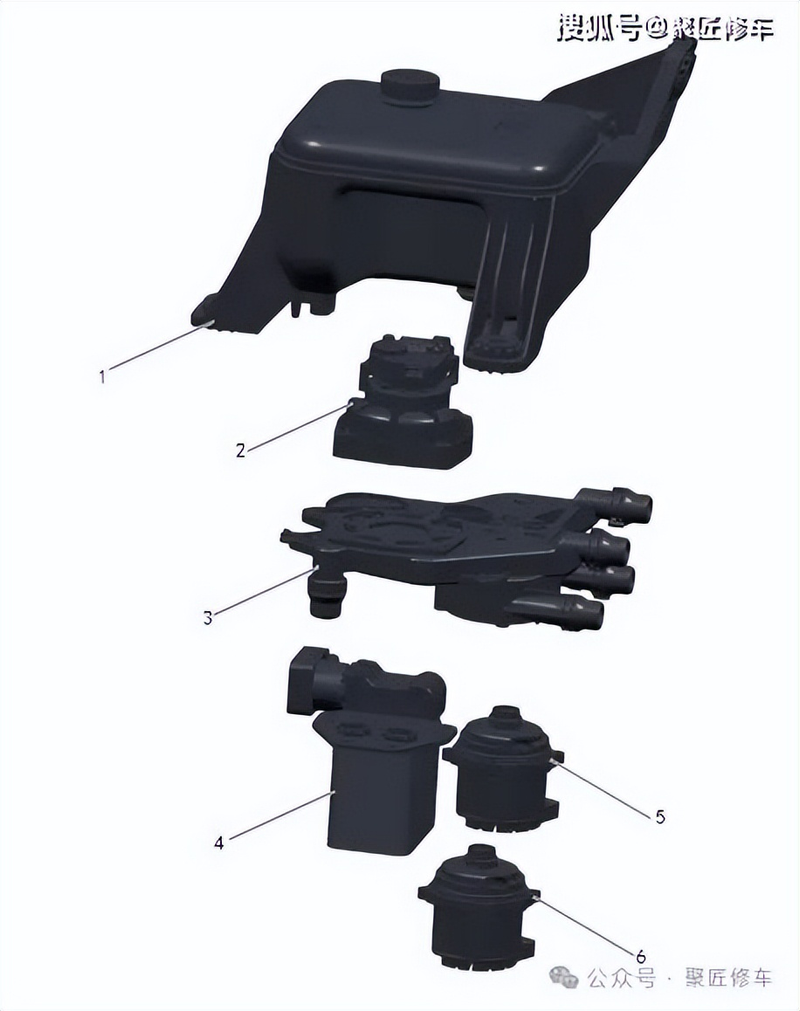
Intelligent expansion of water kettles and multi-component integration of cooling systems reduces the length of cooling pipelines, effectively reduces cooling system failure due to long pipes, and improves the exhaust efficiency of cooling systems。
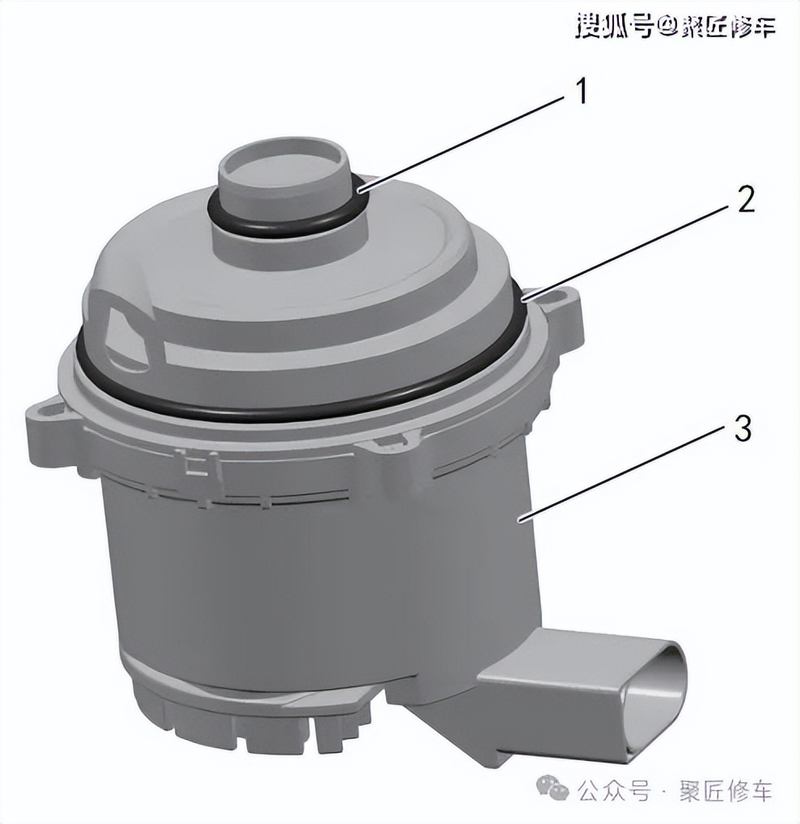
Growing pots
Bulking kettle caps swelling kettle home-type o-pot to fluid tabler sensors
Inflated canteens are used to absorb and resupply cooling fluids, regulate cooling system pressure, and eliminate gases from cooling fluids at the same time。
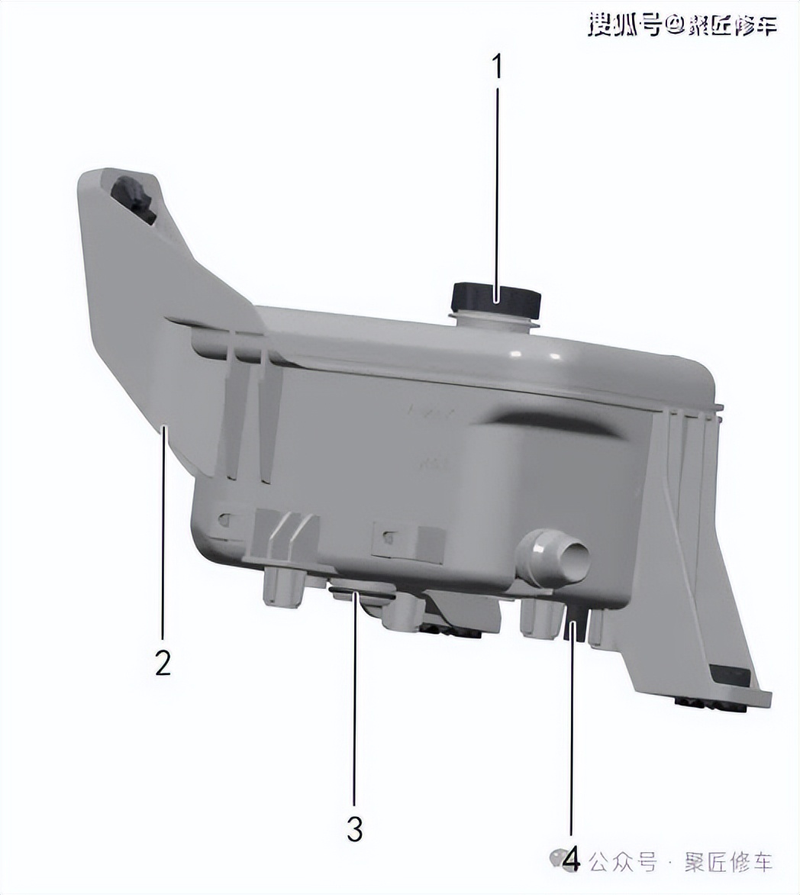
The expansion of the water kettle caps separates the cooling system from the outside atmosphere and increases the pressure of the cooling system as the temperature rises. The increased pressure increases the boiling point of the cooling fluid and the cooling system has a maximum pressure, so an unpressure valve has been installed on the cap of the swelling pot. This will release excessive pressure from cooling systems when maximum work pressure is reached。
The swelling kettle is marked with "max" and "min" scale to facilitate observation of cooling fluid levels。
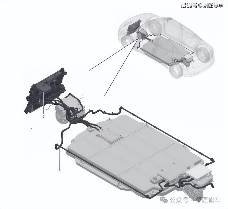
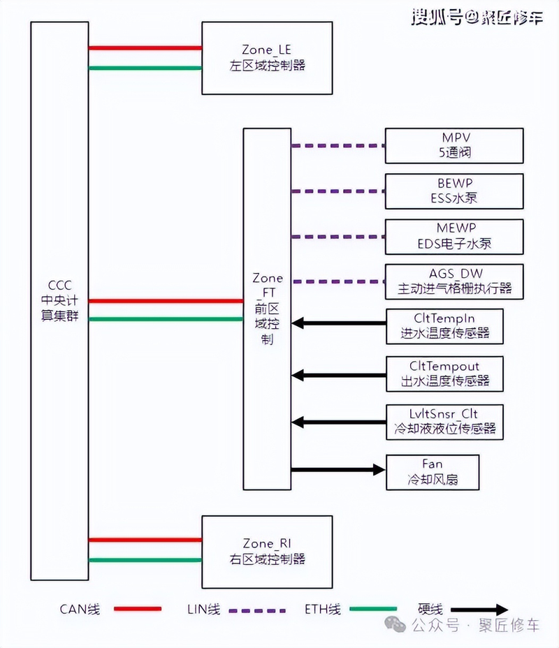
The water canteens are always filled with liquid-level sensors, and when the cooling fluid is too low, a warning light is displayed in the combination table. The water level sensor connects to the 2nd line and transmits the signal to zone ft (former area controller)。
Fluid board
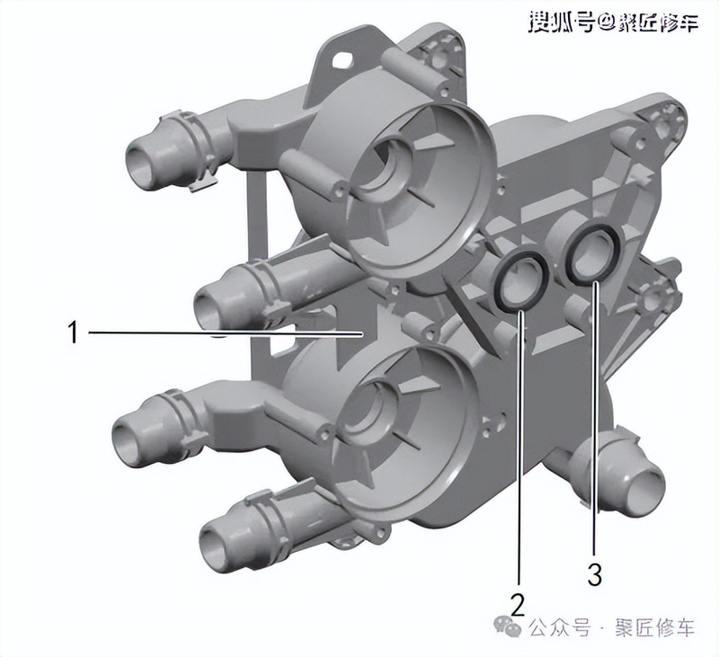
Fluid panels total o-battery cooler entrance to streamboard o-battery cooler exit to flowway board
Cold water pumps
O circle - water pump to flowboard - small o circle - water pump to flowboard - large cooling pump
The cooling pumps are used to press the cooling fluid to ensure its circulation in the cooling system. There are two pumps installed in the system, all of which are bldc (no straight current) with a rated power of 120 w。
The two cooling pumps are primarily responsible for the cooling cycle of the electric-driven system (e. G. Cooling pumps), the cooling cycle of high-pressure batteries (batteries cooling pumps), with different modes of demand and work on their own。
The cooling pump plug-in is a 3-line power, ground and lin-controlled signal line, which is controlled by zone ft (former area controller)。
The pump shell itself has a dent that matches the limit on the stream
Battery cooler
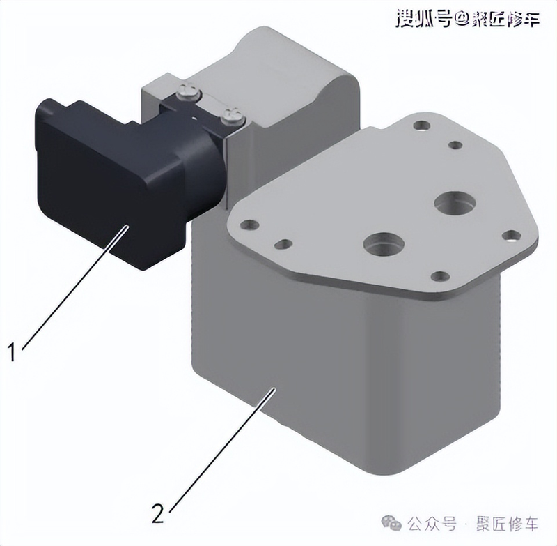
Exv - electronic expansion valve battery cooler home
Battery coolers consist of an expansion valve cut-off valve and a battery cooler home, which are connected to the fluid panels and refrigerant pipes, respectively. Refrigerant and cooling fluid channels are available within chillers, where high-pressure battery packs are sprayed。
The electro-inflation valves are three-line power, ground and lin-controlled signal lines controlled by the zone ft (former area controller) for expansion valve openings。
Cooling temperature sensors
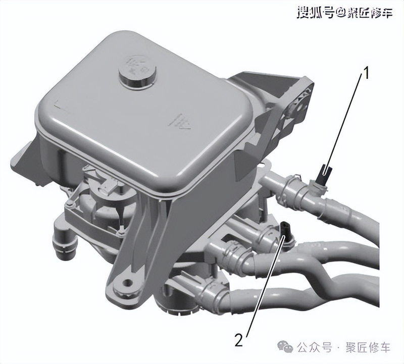
Import cooling fluid temperature sensors export cooling fluid temperature sensing device
There are two cooling liquid temperature sensors in the cooling system for the electric cooling pipe and for the export and import of cooling fluid temperature sensors. Installed back and forth to the interface of the smart swelling kettle pipe with the edsin/edsout. The cooling fluid temperature sensor is ntc (negative temperature factor) thermal sensitivity electrical resistance. Sensors connect to 2 lines to transmit signals to zone ft (former area controller)。
High pressure battery packs have cooling fluid temperature sensors both at the entrance and at the exit to detect high pressure battery pack cooling fluid temperatures。
A cryogenic radiator
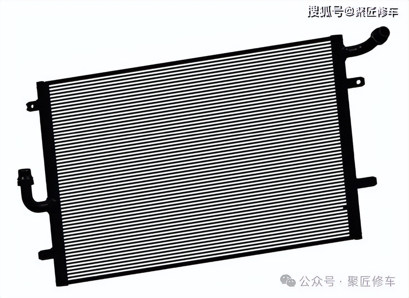
The cryogenic radiator is integrated on the cooling fans, located in the front chamber of the vehicle, and is the main radiator component of the cooling system, with the radiator core using a one-way, transversal process structure, connected to the cooling circuit through a fast plug in the full aluminium water room on both sides. The air flowing through the radiator core is thermally exchanged with high-temperature cooling fluids through flats and wings, thus taking the heat away。
Cool the fan
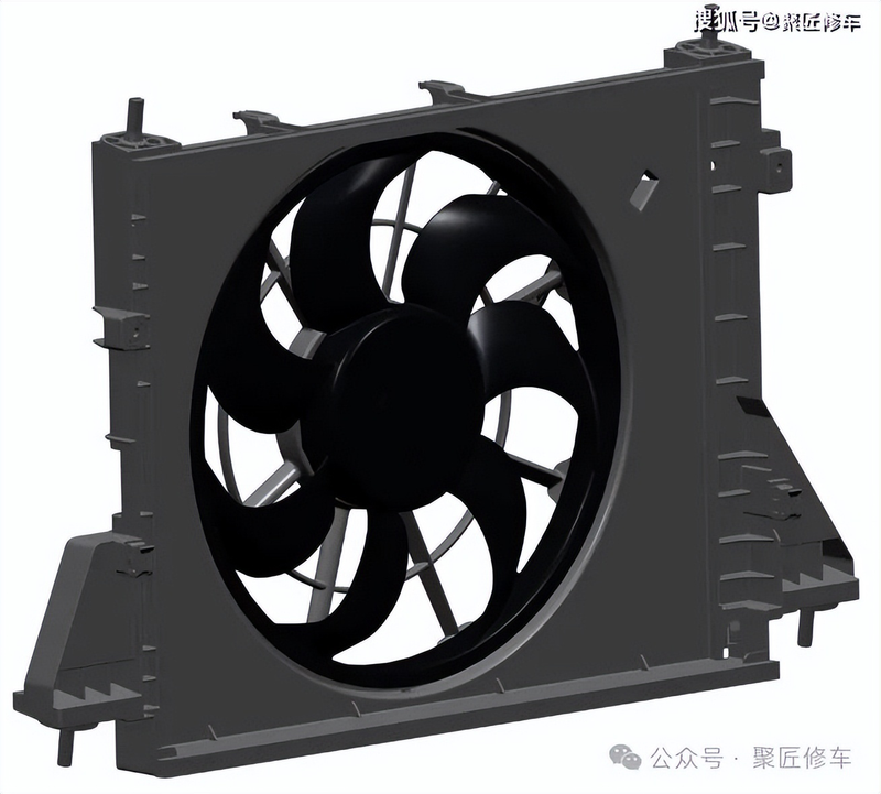
The cooling fan is located in the front chamber of the vehicle and is designed to provide the required amount of wind for cryogenic heaters and outdoor heaters. The cooling fan adjusts the speed of the target by receiving the entire vehicle's pmm signal, and in case of failure the controller pulls down the level feedback against the failure pattern. The cooling fan plug-in is a 3-line power line, a ground line, a signal line。
When you open a fan, you must break the fan beam before it's accidentally damaged by a fast-rotated leaf
Five valves
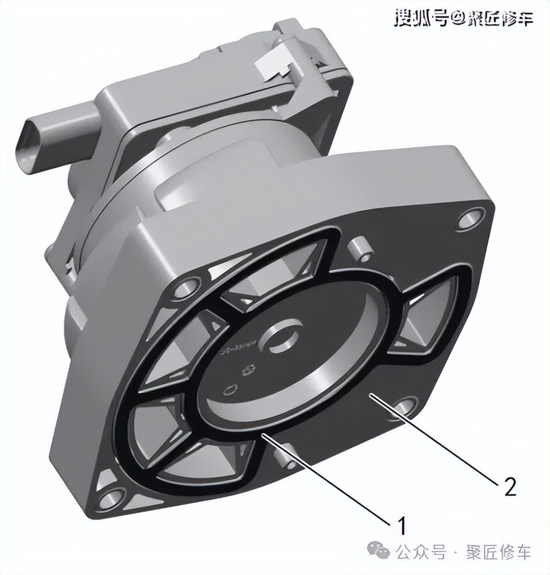
Seal pads - water valves to flowboard five cooling valves
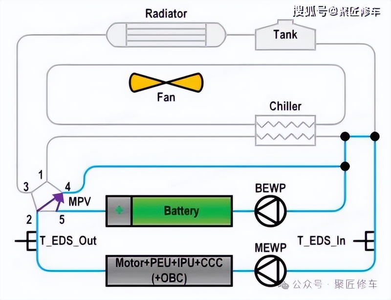
Five water valves are used to switch the loop routes of cooling fluids in the cooling system, with a total of five interfaces, combined with driftboards. There are six states of five valves in the process, as follows:
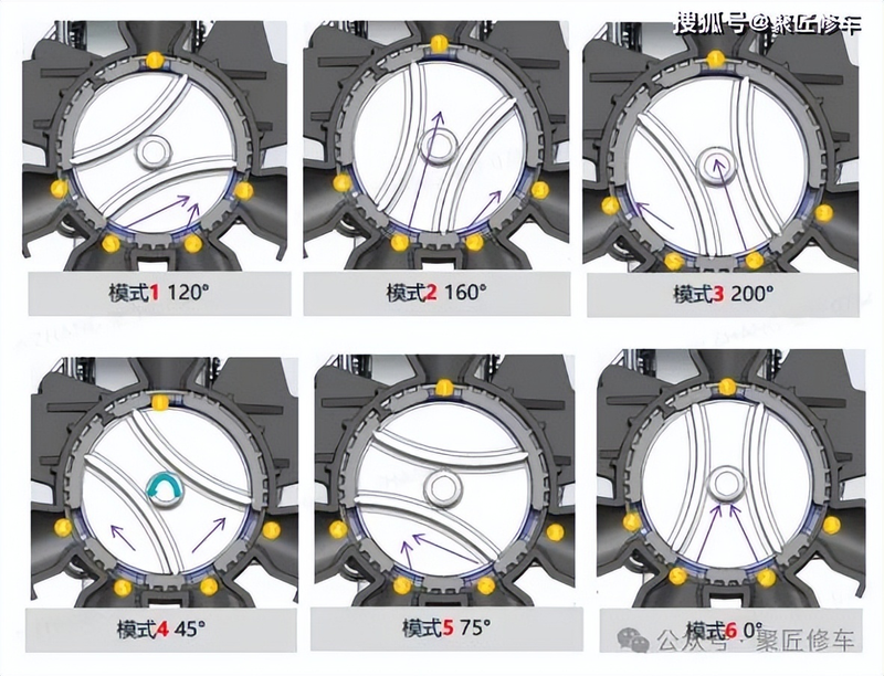
Refrigeration mode + 5-valve eds return eds rotation angle mode 1: electric + battery natural dissipation model 2: electric natural dissipation + battery active cooling < 2 > 1160-mode 3: after-heat recovery + battery average < 2 > 15 > 4200-°4: electric natural dissipation + battery average < 2 & 35 > 445-°5 + battery average temperature < 2 < 45 > 475-°6 : electric + battery average temperature < 2 < 15 + 10 °
Five water valves also have a complete mode (all interfaces are connected) for plant testing and cooling fluid injection。
Five water valves are 3-lined power, ground and lin-controlled signal lines controlled by zone ft (former area controller)。
Cool system cooling mode
Electric + battery natural heating
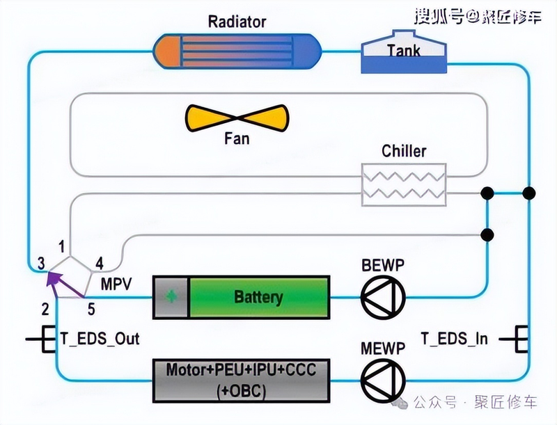
In electric + cell natural dissipation mode, 5 valves are in mode 1 (120°), at which point 5 valves 2, 3 and 5 are connected, with cooling fluids from the electro-refrigeration system and cooling fluids from the battery cooling system not passing the heat exchanger, passing through the external radiator。
Natural dissipation of electrics + active cooling of batteries
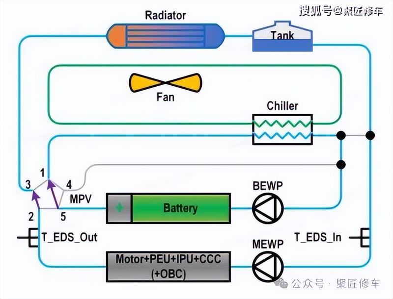
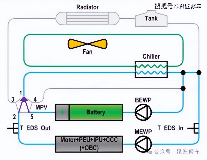
In the natural dissipation + active cooling mode of the electric machine, 5 valves are in mode 2 (160°), at which point the 5 valves 2 and 3 are connected, the cooling fluids of the electro-refrigeration system pass through the external radiator, the 5 valves 1 and 5 are connected, and the cooling fluids of the battery system pass the heater。
Accumulation + battery temperature
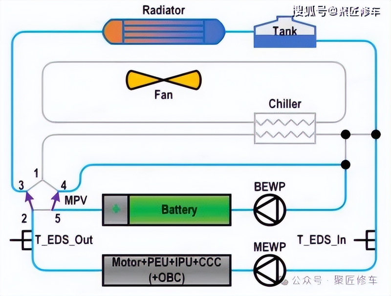
The electrical residual thermal recovery + cell average temperature pattern, with five valves in mode 3 (200°), at which point five valves 1 and 2 are connected, the cooling fluid of the electro-refrigeration system is reheated, five valves 4 and 5, and the cooling fluid of the battery system is not reheated。
Natural dissipation of electric power + average temperature of batteries
In the natural dissipation + cell temperature pattern, five valves are in mode 4 (45°), at which point five valves, two and three, are connected, the cooling fluids of the electro-refrigerated cooling system pass through the external radiator, five valves, four and five are connected, and the cooling fluids of the battery system do not pass the heater。
Electrical heating batteries
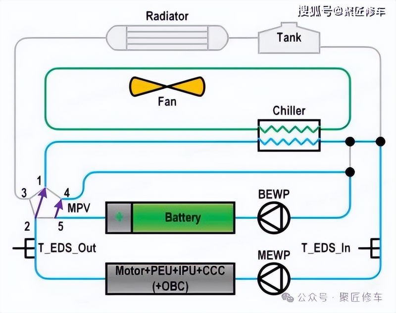
Five valves are in mode 5 (75°) in the electric heating battery mode, at which point five valves 2, 4 and 5 are connected, and the cooling fluids of electric and battery cooling systems do not pass the heater or the external radiator。
Electric + battery temperature
In the thermoquee mode of electrics + batteries, 5 valves are in mode 6 (0°), at which point 5 valves 1, 2 and 5 are connected, with cooling fluids from the electro-refrigerated cooling system and cooling fluids from the battery cooling system passing through the heater, without external heaters。
System control chart
Annotations
High pressure battery pack cooling and heating system control
Zone ft (former area controller) controls the pumps first when they need to be cooled or heated; cooling fluids have different temperatures and pump speeds; when the active heating mode system ceases to work, the control pumps continue to work to avoid excessive gasification of cooling fluids within the pipe。
The cooling mode is controlled when the temperature of the high pressure battery pack is above the nominal control temperature. The cooling mode control will have a lag temperature value, which will stop when the cooling temperature is lower than the late temperature and will be used to eliminate temperature changes during signal switching。
The heating mode is controlled when the temperature of the high pressure battery package is below the nominal control temperature. The heating mode control will have a lag temperature value, and when the cooling temperature is higher than the delayed temperature, the heating mode ceases to eliminate temperature changes during signal switching。
Driver system cooling pumps control
Battery pumps work logic electric pumps work logic
Cooling fan control
When bms has a heat out of control, the fan should be driven to maximum value. When there is no air flow requirement, the fan shall operate at a corresponding rate of rotation to maintain the target wind temperature supply. When the target air flow requires >the flow of air from the active vent and cooling fans to full-time, the cooling fans should be controlled. When vehicle speed >120km/h, the maximum air flow of cooling fans should be controlled according to target air flow requirements and current speed. When it's speed
Ags active air fence control
The ags programme for the active entry of the grid can reduce the aerodynamic resistance, and the ags active grid can change the direction and intake of the flow of air through the lens of a smart electric regulator。
At full power output, heat dispersion is required to be large, and ags completes the grid, increases gas intake and rapidly achieves lower temperatures. In low-power output, heat dispersion requires small amounts, and ags closes the fence and reduces wind resistance. When heating is required, the full ags grid is kept warm。
When bms has a heat outage failure, the ags position is controlled to maximum open (90°). When ags fails or ags fails to learn from itself, the ags position is controlled to maximum opening (90°). When no air flow is required, ags should be controlled for closure. When air flow is required, the opening of ags 6 ~90 should be controlled. When air flow requirements are greater than those of fully open ags and cooling fans, control should be exercised over the full opening of ags。
In the case of a failure of the active intake fence or a card delay, re-initiation is requested, with a maximum allowable number of initializations of two. If both failed, the zone ft pre-area controller controls the ags (preliminary fault) completely open (90°)。


