
Power
In the course of our learning, many of the indicators are direct conceptual indicators, such as we say +5 v for 1, gnd for 0 and so on. But the voltage values in the actual circuit are not entirely accurate, and what are the permissible ranges for these indicators? As we learn more and more, you will slowly develop a capacity to read the data manual。
For example, when we use the stc89c52rc single machine, we find page 11 of its data manual, and see the second -- working voltage: 5. 5 v ~ 3. 4 v (5 v single machine), this place means that the normal working voltage of this single machine is a range, as long as the power of the vcc works between 5. 5 v ~ 3. 4 v, and the voltage above 5. 5 v is absolutely not allowed, it burns the single machine, and if the voltage is below 3. 4 v, it is not damaged, but it cannot work properly. And in this range, the most typical, most commonly used voltage value is 5v, which is the origin of the name "5 v single machine" in the brackets. In addition to this, there is a commonly used working voltage range of 2. 7 v ~ 3. 6 v, typically a single machine of 3. 3 v, known as “3. 3 v single machine”. There will be a deeper understanding of this in the future as more devices become available。
Now let's find out more about the 74hc138 data manual, where you can find a table on the second page of the 74hc138 manual, where the minimum working voltage range of 74hc138 is 4. 75 v, the rated value is 5 v and the maximum is 5. 25 v, and it is known that the working voltage range is 4. 75 v-5. 25 v. One of the most important and authoritative ways in which we can access the working parameters of the device, the data manual, is to access the device。
Jing
Crystal vibration is usually divided into two types: passive crystal vibration, commonly referred to as crystal (crystal), and active crystal vibration, known as oscillator。
It's a full-fledged condensation oscillator, which uses the voltage effect of the quartz crystal, so it needs to be powered, and when we're done with the active crystal vibrator circuit, we don't need to connect to any other device. It can generate a high rate of oscillation, and it can provide a high-precision frequency benchmark, and signal quality is better than a passive signal。
The passive crystal is not able to vibrate itself, and it requires a convulsion circuit inside the chip to work together, allowing for different voltages, but the quality and accuracy of the signal is more variable. Incompetent crystal irritation is much cheaper than active crystal irritation. Both sides usually have a capacitor on either side, usually between 10 pf ~ 40 pf, and if the manual contains requirements for the specific size of the cap, then the capacitor is selected according to the requirements. If the manual does not, we use 20 pf, which is the preferred option, a long-standing empirical value that is extremely relevant。
We've come to see two more common crystallized samples, as shown in figures 8-1 and 8-2。
Figure 8-1
Figure 8-2 crystal vibration figure
There are usually four lures, vcc, gnd, cem and an unused suspension (some also use it as an enabler). If there are two or three triggers, the middle trigger is the shell of the cavity, and when used it is to receive gnd, and the two dots on both sides are torn out of the crystal, which are equivalent, like two dots of electrical resistance, with no positive or negative points. For passive crystal vibration, it is sufficient to connect with two crystal vibrating feet on our single machine, while the crystal vibrate is received only on the input-led feet of the single machine, which do not need to be connected on the output locator, as shown in figures 8-3 and 8-4。
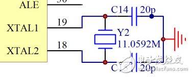
Figure 8-3
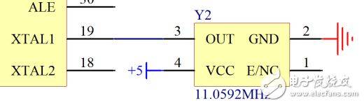
Figure 8-4
Reset circuits
Let's start with a repositioned circuit on the kst-51 board, as shown in figures 8-5。
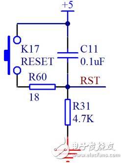
Figure 8-5 mono-branded circuits
When this circuit is stable, the capacitor isolates the direct flow and separates the +5 v, while the double-bit key on the left is ejected, and the lower part of the circuit does not generate the voltage difference, so both the key and the c11 below are equal to gnd, i. E. 0 v. Our single machine is high-altitude, low-altitude working, so normal work is zero v, no problem。
And we're going to analyze the moment when there's no electricity, the c11 upper voltage is 5 v, the bottom is 0 v, and according to what we learned in junior high school, the c11 is going to charge, the positive ion is going to charge from top to bottom, the negative electrons from gnd go up, at this point, the electricity is equivalent to a circuit, the total voltage is attached to r31, so the voltage at the rst port is 5 v, and the currents at the rst and gnd are about to become smaller, and the currents at this point are equal to 0 v。
And in this process, we add this circuit, and when the single-stage system goes on, the rst leads to keep a little bit of the high level of power, and then to low level of power, and this is the process of reconnection. So what's the right time for this? Each single machine is not exactly the same, and the 51 single machine manual contains a duration of not less than two machine cycles. The compound voltage value, which is not exactly the same for each single machine, is complicated by the normal value of 0. 7 vcc as the compound voltage, and i'll give you only one conclusion: time = 1. 2 rc, we use r is 4700 euro, c is 0. 0010001, so the calculation t is 0. 000564 seconds, i. E. 564 us, which is much more than two machine cycles (2 us) and usually leaves enough excess in circuit design。
There are two processes at the key repetition (i. E., manual re-entry) where rst's voltage is 0 v before the button is pressed, and when the key is pressed, the circuital conductor is activated at the same time, while the face is discharged at the same time, and the rst's voltage values change to 4700 vcc/(4700+18), and is in high-level re-entry status. When you unplug the button, it is similar to the retweeting position, first charged with the cap, then the current decreases until the rst voltage transforms 0 v. We usually have hundreds of milliseconds to press the button, and this time is enough to reset。
When the button is pressed, the 5v voltage (not between 5v and gnd, which is not a power source) at both ends of the capacitor will be connected directly, and at this point there will be a sudden shock of large currents, which will cause local electromagnetic interference, and in order to contain the disturbance caused by this large current, we are here to link an 18-eu blockage to limit the flow。
And if some of the students have tried to start diy and design their own circuit boards, there's already enough theoretical basis for the design of the mini-mechanical. Students with less basic needs continue to follow their studies and finish their courses before it is too late。


