Simple switch power circuit (i) simple and functional switch power circuit figure
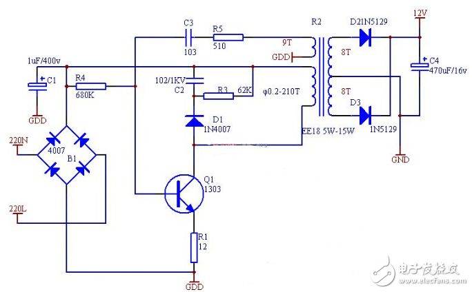
Adjustment of c3 and r5 to oscillation frequency 30khz-45khz. Output voltage requires steady pressure. Output currents can reach an effective power of 8w at 500ma. And efficiency of 87%. The others can work without a request。
Simple switch power circuit (ii)
The 24v switch power is a type of high frequency reverse switch power. High-speed routing and cut-off through circuit control switches... Conversion of direct currents to high-frequency communication power for transformers to generate the required group or groups of voltages
24v switch power works:
1. Exchange power input filtering straight through flow;
The direct flow is added to the primary switch transformer through the high frequency pwm (pulse width) signal control switch;
3. Switch transformer sub-sensor emits high frequency voltage, which is filtered through the current filter load;
4. The output component is fed back to control the circuits through certain circuits and control the pwm ratio to the point of stabilizing the output。
24v switch power circuit
24v flow protection map
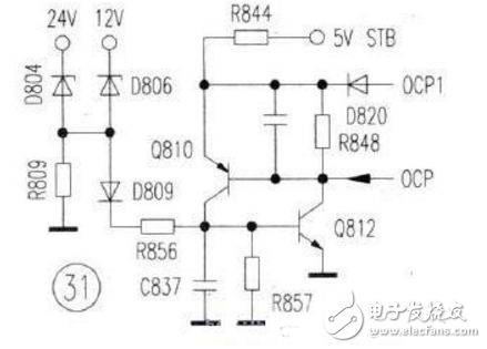
24v pressure protection map
Simple switch power circuit (iii)
The typical circuits for single-end active switches are shown in figure iv. This circuit is formally similar to a single-end introgen circuit, but works differently. When the switch pipe vt1 leads, vd2 too
Transmitting, at this time, the grid transmits energy to the load, which is stored in the filter sense l; when the switch tube vt1 is closed, the sensor l continues to release energy from the load by renewing the diode vd3。
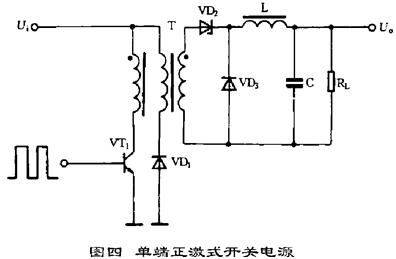
There are also plier wires and diode vd2 on the circuit, which can limit the maximum voltage of the switch tube vt1 to twice the power voltage. To meet the magnetic core co-location condition, i. E. Magnetic ducts set up and
The repositioning time should be equal, so the ratio of pulses in circuits cannot be greater than 50 per cent. Since this circuit transmits energy to the load through transformers when the switch pipe vt1 is in operation, the output power range is large and can be 50-200 w. The transformers used by circuits are complex in structure and larger in size, which is why they are less applied in practice。
Simple switch power circuit (iv)
The typical circuits for the switch are shown in figure vi. It is a two-end transformer circuit, and the magnetic core of the high-frequency transformer works on both sides of the magnetic detour line. The circuits used two switches, vt1 and vt2, which rotated between the control and cut-off of the external incentivizing side wave signals, and received a wave voltage at the transformer t sub-group, which was converted to the required direct current voltage。
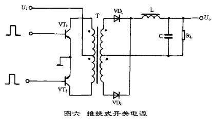
The advantage of such circuits is that two switches are easily driven and the main disadvantage is that they have to have twice as much tolerance as the peak of the circuit. The output power of circuits is high, generally in the 100-500 w range。
Simple switch power circuit (v)
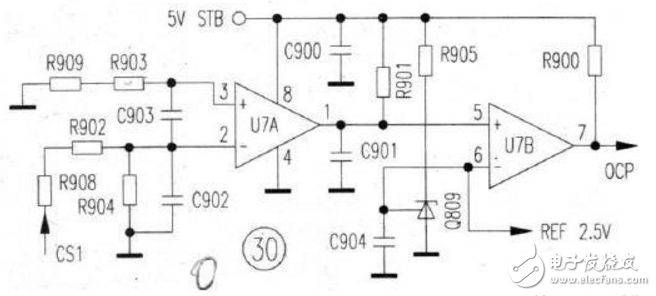
The power feed backsegregation circuits in the switch power are made up of pv couplings such as pc817 and co-pressurizer tl431, with typical applications as shown in figure 3. When the output voltage fluctuates, the sample voltage is compared with the 2. 5v lacquer baseline voltage in tl 431, resulting in an error voltage in the cathode, resulting in a corresponding change in the production of led working currents in the photocoding device, changing the current size of the topswitch control via the photocoding device, and thus adjusting the output ratio to the empty ratio so that the uo remains intact for the purpose of steady pressure。
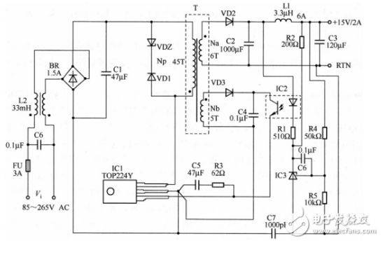
Figure 3
The role and selection of the main elements in the feedback circuit: r1r4r5 works primarily with tl431 and the photocoding device, of which r1 is a photolytic restricted electrical resistance, r4 and r5 is a sub-voltage electrical resistance for tl431 and must work to complete tl431 protection。
Simple switch power circuit (vi)
The circuit is centred on the uc3842 oscillation chip and constitutes a reverse, whole current circuit. Uc3842, a high-performance single-end output-control pulser chip, is described in terms of foot-leading functions and internal circuit principles, which are omitted here. The introduction of the ac220v power source co-mode filter l1 better inhibits high-frequency interference from the grid and from the power source itself to radiation, the exchange of voltage through the bridge-to-wire circuit, and the convalescent c4 filter has become an unstable direct current voltage of approximately 280v as a reverse circuit consisting of oscillating chip u1, switch q1, switch transformer t1 and other components. The reverse circuits can be divided into four circuit sections that explain their circuit operation。
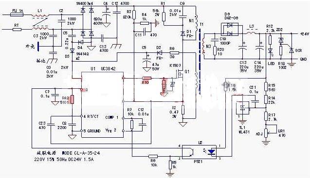
Figure 1 dc24v power source for cl-a-35-24
Oscillation circuits: leaks in the main circuit group n1, q1 of the switch transformer - source pole, r2 (work current detection resistance) are circuits for working currents of the power supply; (a) unlike other switches (starting circuits consisting of relief-restricted current resistance), start-up circuits consist of c5, d3 and d4, providing an “immediate” start-up current, diode d2 absorbs reverse voltage, d3 has a condensive effect and guarantees that the start-up current added to the foot of u1 is positive; when the circuit is boosted, n2 provides the power voltage for the u1 chip by means of a self-electrical circuit, d2 and c5 filtering circuits. The proper functioning of these three links is a prerequisite for the power to be able to shake。
Of course, the four-foot timing components r48, c8 and u1 are themselves part of the oscillation circuit。
Capable-activated circuits, which, when overloaded or short-circuit failure occurs, are in a stable state of static protection, unlike resistance-activated circuits, re-emergence of hiccups. (b) work-flow detection was obtained from electrical resistance r2, and when the malfunction caused an abnormal increase in work overflow, the 6-foot output pwm pulse of u1 was reduced, and the n1 self-electrical circuit was reduced, and when the 7-foot power supply voltage was below 10v, the circuit was shut down and the load was zero, which was the suspension of output caused by the overflow (overload or short-circuit) which triggered the failure of the u1 internal voltage protection circuit; in the event of an abnormal increase in the current at work, when the voltage on r2 is reduced by more than 1 v, the internal locker action, the circuit is disabled, which is the result of the suspension of the output as a result of an internal overflow protection action triggered by the flow。
2. Steady pressure circuit: the n3 circuit, d6, c13, c14, etc. Of the switch transformer, and the base voltage source tl1, photocoding u2 form the pressure control circuit. U1 chips and foot exterior components r7, c12 are also part of the steady-pressure circuit. In fact, tl1, u1 formed an external error amplifier (as opposed to the internal voltage error amplifier of u1) that fed back to the u1 feedback on the 24v voltage change. When the 24v output voltage rises, the 2-foot voltage of u1 rises, the 1-foot voltage drops, the output pwm pulse drops, and the output circuit falls back. When the output voltage rises abnormally, the foot of u1 falls to 1v, the internal protected circuit movement is interrupted。
3. Protection of circuits: the u1 chip itself and the three foot outer circuits constitute a passing protection circuit; the d1, r1 and c9 components, which are combined on the n1 circuit, form the reverse voltage absorption protection circuit in the switch to provide reverse circuits at the end of q1 and to ensure the safety of q1's work; the voltage feedback signal for the substantially stable circuit can also be considered as a shock protection signal along the way - the circuit is suspended when the feedback voltage reaches a certain value; the output end of 24v is accompanied by a voltage-protected circuit consisting of r18, zd2 and a one-way crystal line scr, which provides a trigger current for scr when a steady voltage circuit is irregular, causing an abnormal increase in the output voltage, and a steady zd2 penetration provides scr with a “short-circuit current” signal, forcing u1 internal protection of the circuit to generate a permeable protection action, and the circuit is in a state of shock。