
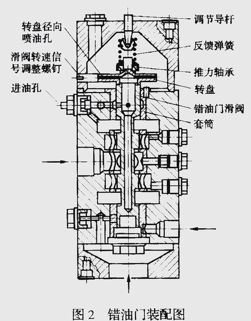
1. The oil motive works in the wrong way. Or oil motive includes the wrong door. (i) changes in pulsed oils cause the wrong valve core to move up and down, control the pressure oil into the upper and lower cavities of the tank, drive the piston movement and regulate the opening of the doors. At the same time, feedback components, such as feedback boards, pass the piston movement (reverse) to the feedback spring on the valve core, which returns to its middle position with increased feedback spring. This means that a certain pulsed oil-pressor will have some piston process output. The ratio relationship between pulse oil and piston travel can be changed by changing the slope of the feedback guidance board. (2) the rotation and vibration of the wrong valve core. The pressure oil enters the core of the human valve through the internal channel and then ejects to the hole from the wheel drive, which rotates the core. Snail 18 can change rotation speed (generally 600,900r/min) by regulating the amount of spray oil。
2. In addition, in order to further increase the sensitivity of the oil-motive motion, it is also vibrating when the wrong valve core is rotated. A small hole in the lower core of the valve, which rotates every time, the pulse oil is connected to the back hole, which causes the core to shake and triggers a slight vibration from the oil-driven output. This would avoid slow response from the system. Snail 15 is used to adjust the amplitude. (3) because the vapour-regulated doors are typically multi-valved butterfly structures with different shapes and opening sequences, and given the different opening properties of the valves, single butterflies and the non-linear curves of the entire door characteristics require that the oil-motive feedback plate line type should be specially designed for that characteristic curve (one machine, one line), to compensate for the non-linearity of the valve-regulating and to keep speed control as smooth as possible. The faulty engine structure and the oil system controlled by the main engine door, as shown in the chart, consists mainly of the server valve, the offload valve, the oil motive, the oil motive entering the tank and opening the door, the oil motive being connected with the pressure back, and the upper part of the car door having the compound
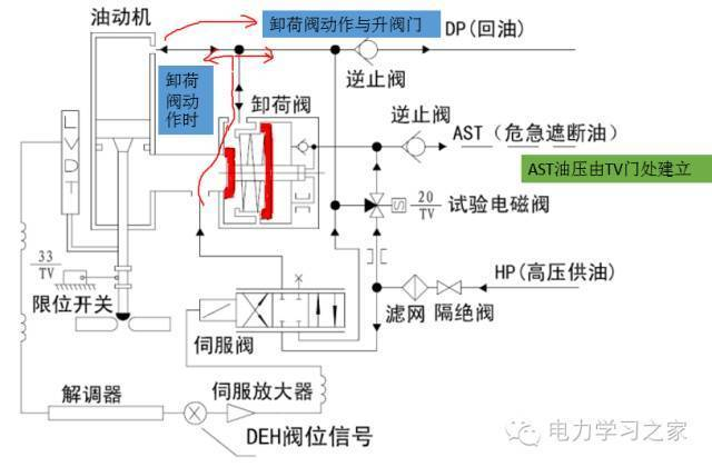
3. Springs, when the oil-motion tank leaks, the gas door closes the door under the effect of the upper spring response, the oil-motion tank enters or spills under the control of the server valve, and the server valve receives the telecommunication number driven by the server card, controls the intake or discharge of the server valve, shuts down the brakes to cover the movement of the electromagnetic valve, releases the safety pressure (ast pressure), when the discharge valve opens, the gas-moves the tank presses through the upper spring response, and the main engine closes rapidly with the spring response, so that, after normal shutdown, the oil-movement cask and the pressure back. The basic characteristics of the electron server valve 3. 4. 1 enter the current-output flow characteristics the relationship between the output flow and the input signal currents when they are airborne is commonly expressed in the space-borne flow characteristics curve (figure 32). Characteristics such as rating values, linearity, molar rings, flow gain are derived from this curve. The rated current ir is in this current range, and the output flow of the valve is right with the incoming signal
Four. The rated traffic is in the air traffic of the rated pressure and rated current valves. Measure of linear q-i curve straightness. The demurrage rings are used mainly to indicate the degree to which the i-q curve does not overlap for reasons such as friction, magnetism, etc. When the signal current changes direction. Often expressed as the ratio of imax to the rated current ir of the valve with the maximum current in the same flow. The flow gain ql-i ratio, the average slope of the q-i curve. 3. 4. 2 pressure gain properties the margin pl/i is referred to as pressure gain at input current i and load pressure pl = p1p2 curves under a specified oil supply pressure. When the load flow remains zero, pressure gain near zero (median balance position) is called zero pressure gain. The zero pressure gain is related to the opening form of the main slide valve, which is the highest in zero. Increased oil pressure ps could also increase zero pressure gain. But this feature is mainly related to the manufacture of valves. Mass
5. Volume-related. Increases in zero pressure gain have been instrumental in reducing insensitive areas and improving accuracy, but have been counterproductive to stability. Figure 33 shows the zero-digit pressure gain characterization curve for the zero-open-server valve. 3. 4. 3 load pressure, flow characteristics, which are often the main basis for the selection of the server valve. Figure 34 is the load pressure-flow characterization curve. 3. 4. 4 a logarithmic frequency feature. The frequency of a 3db in the band curve is the width of the valve. The greater the value, the greater the frequency of the valve. The logarithmic frequency characteristics are also the basis for the analysis of the dynamic properties of the server system and the design and integration of the electron server system. 3. 4. 5 zero drift and zero bias zero change of the server valve (geometric position of ql=pl=0) due to changes in the pressure for oil and the temperature of the working oil is referred to as zero drift. Zero voltage is generally measured by the ratio of current value to rated current value required to restore its position. The smaller the value, the better. In addition, because of differences in manufacture, adaptation and assembly, the slide valves are not necessarily in the middle when the current is not present in the chain of control. Sometimes a certain amount of current must be added to restore it to the median (zero). This phenomenon is called zero bias. Zero is measured by the ratio of current value to rated current value required to restore zero to the valve. 3. 4. 6 insensitivity due to the presence of insensitive areas, the server valve will change its state only when the input signal current reaches a certain value. The minimum current to rated current ratio for changing the condition of the server valve is described as insensitivity. The smaller the value, the better. Source: network of 3 hydraulic components.


