
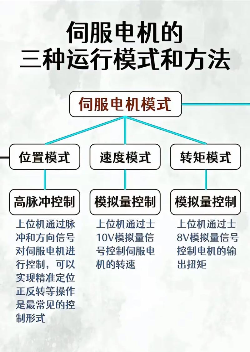
1. Initialization parameters prior to wiring. On the control card: choose the control method; clear the pid parameters to zero; disable the energy signal by default when the control card is powered; and save the status to ensure that the control card is re-charged for this purpose. On the server: set controls; set enablers to be externally controlled; codifier signal output gear ratio; set the control signal ratio to the electric retrofit. In general, it is recommended that the maximum design speed for the server should correspond to the 9v control voltage。
2. The connection will control the blackout of the card and connect the signal line between the control card and the server. The following lines are required: analogue output lines for control cards, enabling signal lines and encoder lines for servicing output. Following a review of the connection, the electrical and control cards (and pc) were installed. At this point, the power should remain intact and can be easily rotated by external force, if not, checking the configuration and connection of the enabling signal。
3. The test direction is catastrophic for a closed loop control system if the feedback signal is not in the right direction. Opens the serviator signal through the control card. It's a service that should be moving at a lower rate, and that's the legendary “zero drift”. The general control card contains commands or parameters that inhibit zero drift. Using this command or parameter, the speed and direction of the viewer is controlled by this command (parameter). If you cannot control it, check the parameter setting of the analogue and the mode of control. Confirms that positive numbers are given, the electrics are turning, the encoder counts are increased; negative numbers are given, the electrics reverse, the encoder counts are reduced. If the power is loaded and travel is limited, this method should not be used. Tests do not give excessive voltage and are recommended below 1v. If the direction is inconsistent, the parameters on the control card or on the electric power can be modified to make them consistent。
4. The containment of zero drift during the closed circle control process, the presence of which has some effect on the control effect, is best contained. Use control cards or non-floating parameters on the server, carefully calibrated to bring the electric power closer to zero. Since zero drift itself is somewhat random, it is not necessary to require an absolute zero speed switch。
5. Establishing a closed loop control once again releases the server signal through the control card and enters a smaller percentage gain on the control card, which can only be felt if it does not feel comfortable, the minimum value allowed by the control card. Opens the control card and the server's enabling signal. At this point, the electric power should have been able to act broadly in accordance with the motion order。
Six, adjust the closed-ring parameters fine-tune the control parameters to ensure that the electric power moves in accordance with the control card's instructions, which is something that has to be done, and this part of the work, more experience, can only be omitted。
7. Axis load a: ensure that, at the time of installation and operation, the routing and axial loads on the server axis are kept within the specified values of each model. B: be particularly careful when installing a rigid axis, especially when excessive bending loads may lead to damage or wear of the axis and bearings. C: it is advisable to use flexible axes so that the direction load is below the permissible value, which is specially designed for high mechanical strength servers. D: for permitted axle load, please refer to the “permissible axle load table” (use instructions). Server installation note a: do not hit the axis directly with a hammer while installing/dismantling the assembly component to the server axis. (the hammer hits the axis directly and the encoder on the other side of the engine is to be broken) b: try to align the axis to its optimal state (which may cause vibration or damage to the bearing)。


