Relax the debugging steps
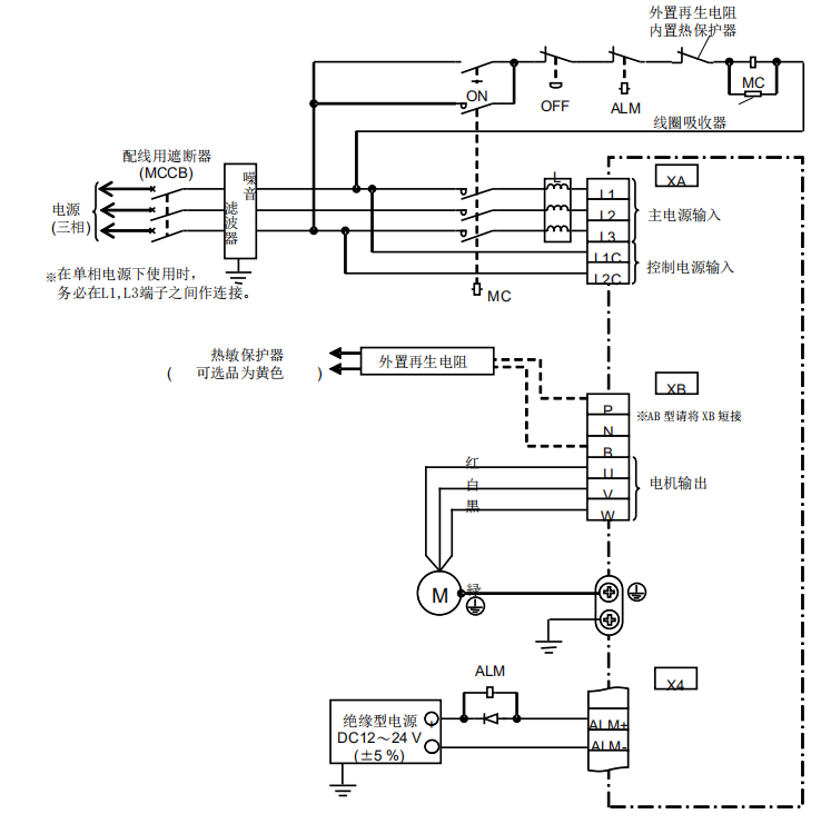
1. Connect drives consist mainly of control circuit power, primary control circuit power, controller interface x4, external migration sensor interface x5, encoder x6。
Lines for power connectors and consoles
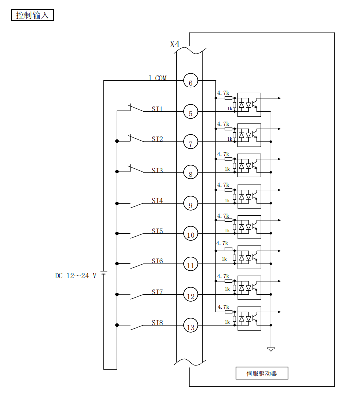
Line for connector x4
Control input
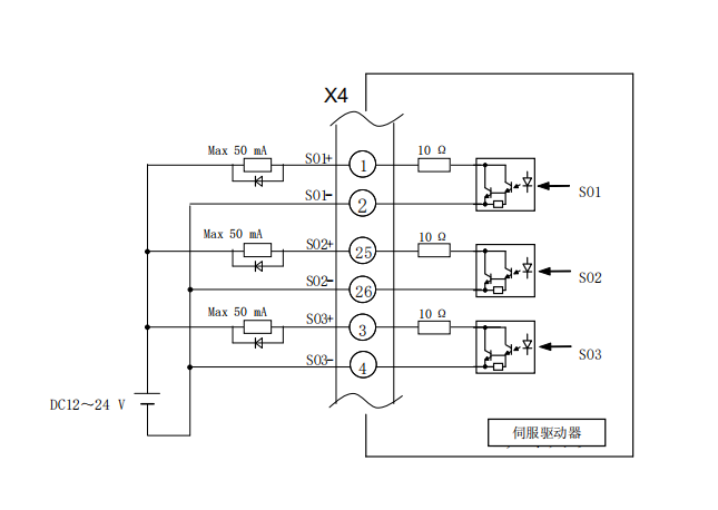
Control output
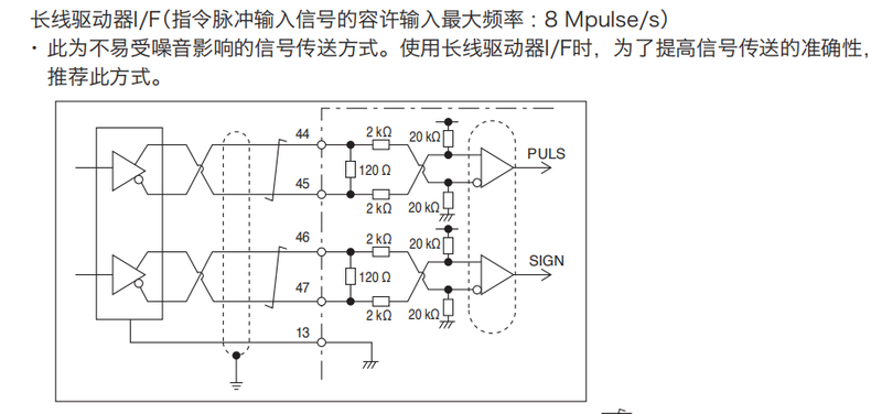
Long-line drive special pulse chain interface
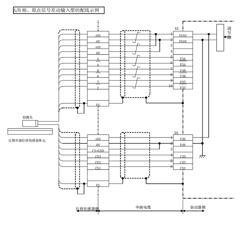
Line for connector x5 x6
2. Automatic setting of straight-line electric units using tools
Using the motor autosetup tool, you can automatically set the initial parameters corresponding to the linear power mix (electrical gain, raster direction, cs direction). (with regard to the radio automatic setting tool, consult loose appliances
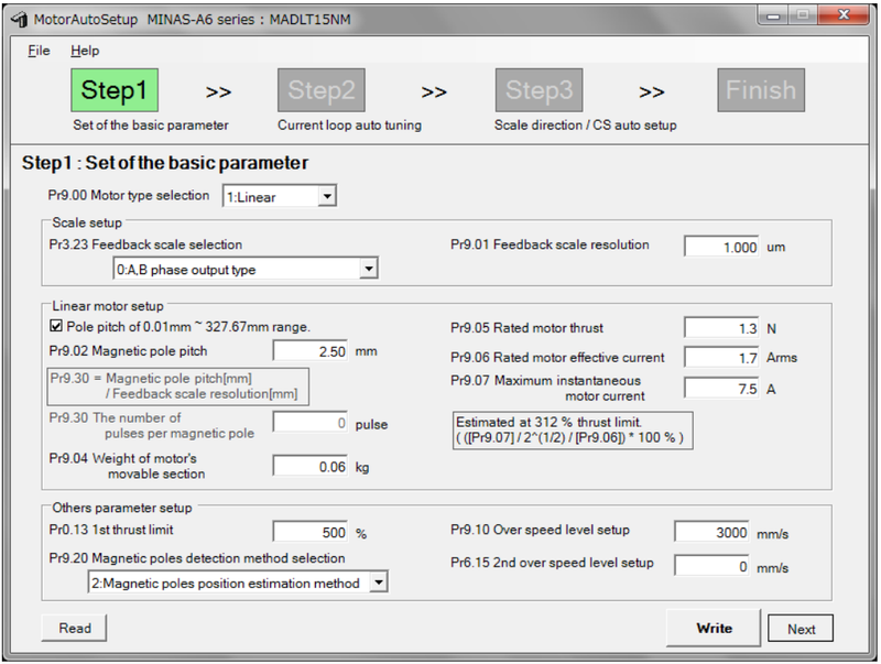
If automatic settings are started, the servo enabler will automatically set the linear power, so the linear power opportunities will act. Autoset automatically to turn to server after completion。
Automatically set the power of the last-placed server driver。
(for the method of use of the linear power-set tool, please refer to the step book attached to the tool
3. Set orientation and electronic gear ratio
Direction setting
The direction of electrical manoeuvres can be switched to the direction of the position/velocity/reverse command。
Associated parameters
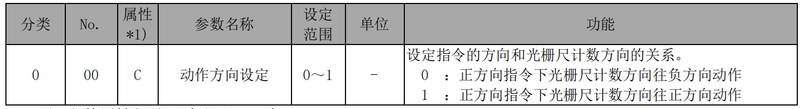
Pr0. 00 "action direction setting" is set according to the following steps。
Step 1
First, set pre 3. 26 "reverse the direction of the raster"。
Set the method by reference to the direction of the 4-7-1-4 raster。
Set to write to eeprom and connect to the power source again。
Step 2
Set pr0. 00=1, write in eeprom and then connect again to the power source。
(pr0. 00 = 1 for the plant, and this step is not required if the plant is out
Step 3
In case you are able to shut down (the electrical power is off), move the power in the direction that you wish to use as the device。
Please confirm the direction of the raster count at this time, and if that direction is negative, set pr0. 00=0 and, if positive, pr0. 00=1. Set to write to eeprom and connect to the power source again。
The direction of a raster ruler may be confirmed by the sum of the pulse of the raster ruler in the front monitor (reference 3-2-1 (6)) or by the direction of the value of the "sum of the raster ruler pulse" in the panaterm image。
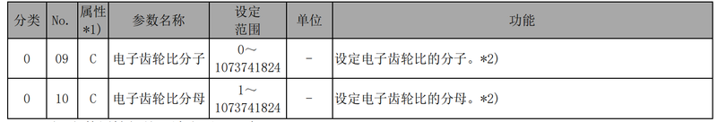
Electronic gear ratio
Adds the electronic gear ratio set by the object to the position command entered from the top controller and uses this value as the function of the position control section. By using this function, you can set the number of rotations/ moves of generators in a given unit。
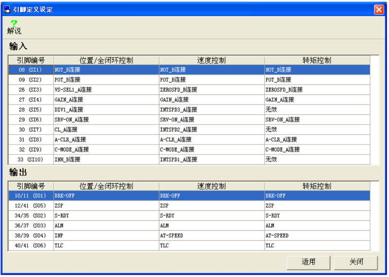
4. Distribution of output-input signals
Sets the image to assign the function of input-output-inducing。
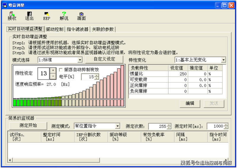
5. Automatic adjustment gains
Gain adjustments can be used to make automatic adjustments to the drive. Simple monitors can be used for automatic measurement as adjustment indicators. The server gain adjustment is the same as the normal rotation server adjustment。