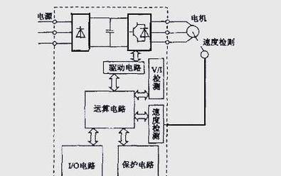
The frequency transformer is the exchange power that converts the industrial frequency power (50 hz or 60 hz) into a variety of frequencies in order to achieve the speed of the power plant, which controls the circuits to complete control of the main circuit, converts the current circuits to a straight current, smooths the direct middle circuits to the output of the whole circuit, and reverses the current to the communication. In the case of a vector control variable, which requires a large amount of computing, there is sometimes a need for a cpu with a rectangular calculation and some corresponding circuits. The modulus speed is achieved by changing the frequency of the power supply by the fixed circuit。
The variable frequency technology was born in response to the need to communicate the electrons' incalculability. After the 1960s, electrical electronics went through the development of scr (stiplining tube), gto (extremely closed transistor), bjt (bipolar power transistor), mosfet (metallic oxide field effect tube), sit (static transistor), sith (static transistor), mgt (mos control transistor), mct (mos control transistor), igbt (insulation fence, bipolar transistorption) and hvigbt (hvigbt resistance to high-pressure insulation fence, bipolar crystallation tube), and the updating of the device contributed to the continued development of electrical conversion technology. Starting in the 1970s, the velocity studies of pulsed transformer frequencies (pwm-vvvvf) were given high priority. In the 1980s, the optimization of the pwm model, which is the core of the variable frequency technology, attracted considerable interest and resulted in a number of optimising models, among which the best was the saddle wave pwm model. Starting in the second half of the 1980s, vvvvf variants from developed countries such as the united states, japan, germany and the united kingdom were put on the market and widely used。
There are a variety of methods for the classification of variants, which can be classified as electrical and current variants according to the mode of operation of the main circuit; as pam control variants, pwm control variants and high-load frequency pwm control variants, which can be classified as v/f control variants, spin-off frequency control varianters and vector control varianters, which can be classified as universal, high-performance private, high-frequency, single-phase and triple-phase varianters, according to the method of work。
Vvvf: change the voltage, change the frequency cvcf: constant voltage, constant frequency. Countries use the power supply for communication, whether for domestic use or in factories, with a voltage and frequency of 400 v/50 hz or 200 v/60 hz (50 hz), etc. Typically, a device that converts the voltage and frequency constant to a voltage or frequency variable is called a "frequency transformer". In order to generate variable voltage and frequencies, the equipment first converts the power exchange to direct current (dc)。
Frequency transformers for electrical control can change both voltage and frequency。
The work of the frequency transformer
We know the synchronous velocity expression of communication motors:
N=60 f(1-s)/p(1)
Where
N - the speed of the different electric motor
F- — frequency of a different electric motor
S—electro-drive rate
P - electro-motive polar logarithm。
By formula (1), the rate n is proportional to the frequency f, which changes the rate of the motor when the frequency f changes in the range of 0 to 50 hz. The speed adjustment is achieved by changing the frequency of the power source of the motor, and is an ideal efficient, high-performance speed-reducing tool。
Frequency changer control
The low-pressure generic variable frequency output voltage is 380-650v, with an output power of 0. 75-400kw and a working frequency of 0-400hz, and its main circuits are trans-tangible. The way in which it was controlled went through the following four generations。
1u/f=c sinewire (spwm) control mode
It is characterized by simple, low-cost circuit control structures and better mechanical rigidity, which meet the generally moving smooth-pacing requirements and has been widely applied in various areas of the industry. However, at low frequency, this mode of control reduces the maximum rectangular output due to lower output voltage and the relatively significant impact of the rectangular rectangular relief. In addition, its mechanical properties end up without a straight-flowing motor hard, a dynamic rectangular capacity and static retrenchment performance that are not as satisfactory as expected, a weak system, a control curve that changes with loads, slow rectangular response, low use of electric rectangulars, reduced performance at low speeds due to the presence of stationary resistance and retrovert effects, and reduced stability. Therefore, vector control variants are being studied。
2 pressure space vector (svpwm) control method
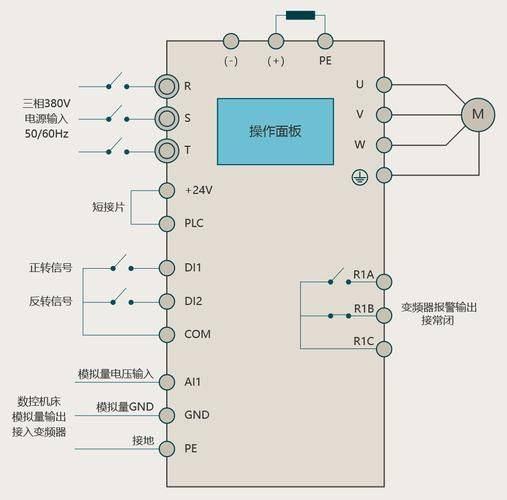
It is premised on the effect of a three-way phase as a whole, which produces a three-phase waveform at a time to be controlled by an incisive polygon as an approach to a close circle, with the aim of closing the desired circle magnetic field trajectory of the electromechanical gas. This has been improved after practical use by introducing frequency compensation, which eliminates errors in speed control; by estimating magnetic chain bands through feedback, by eliminating the effects of stationary electrical resistance at low speed; and by increasing the accuracy and stability of the dynamic by exporting voltage, current loops. However, the system has not been fundamentally improved because of the relatively large number of circuits controlled and the absence of a rectangular regulation。
Vector control (vc) method
Vector control of variable-frequency velocity is the practice of changing the constant current ia, ib, ic, which is under the three-phase grids, into the exchange current ia1 ib1, which is under the three-phase phase, and the direct current im1 and it1 (im1 corresponds to the direct current motor; it1 is equivalent to the current current that is positive to the transliteration sequence), and then imitates the control method of the direct current motor, so as to obtain control over the direct current motor, through the reverse conversion of the corresponding coordinates, and achieve control over the opposite motor. The essence of this is to communicate the equivalent equivalence as a direct current motor, with independent control of speed and two parts of magnetic field, respectively. By controlling the trans-magnetic chain, and then dissecting the sub-electrical current, it obtains both the rectangular and the magnetic field fractions, which are changed by coordinates, and achieves positive or decomposition control. The introduction of vector control methods is a landmark. In practical applications, however, because of the difficulty of accurately observing the rotor magnetic chain, the system characteristics are more affected by the electrical motor parameters and the complexity of the vector rotation used in the control of straight current motors makes it difficult to achieve the desired results of the actual control。
Direct control (dtc) method
In 1985, professor depenbrock of the university of ruhr, germany, first proposed direct rectangular frequency control. To a large extent, the technology has addressed the above-mentioned deficiencies in vector control and has been rapidly developed with innovative control ideas, a concise system structure, and good kinetic staticity. At present, the technology has been successfully applied in connection with the high power exchange of electric tractors. Direct rectangular control analyses mathematical models for the exchange of electric motors directly under the fixed-coordinate system, and controls the magnetic chain and rectangulars of electric motors. It does not need to equate the exchange motor with the direct flow motor, thus eliminating many of the complex calculations in the vector rotation conversion; it does not need to imitate the control of the direct flow motor or to simplify the mathematical model of the communication motor for decoupling。
Quasi-control mode
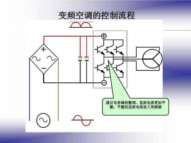
Vvvf variants, vector control variants, and direct rectangular control variants are all one of the t-r-r. The common disadvantage is that the input power factor is low, the current current is high, the direct current circuit requires a large storage capacity, and the renewable energy does not feed back into the grid, i. E. It cannot operate at a four-dimensional limit. To that end, matrix-transformation-transformation frequency flows. The matrix-transformation frequency saves the middle straight stream, thus saving large and expensive electroly decomposition. It achieves a power factor of l, enters a current that is a sine and operates at a four-dimensional limit and has a high power density of the system. While the technology is not yet mature, it still attracts in-depth research by a large number of scholars. The substance is not indirectly the control of currents, magnetic chain equivalents, but is achieved directly as controlled quantities. This will be done by:
• control of the introduction of a fixed magnetic chain monitor to achieve a speedless sensor approach
- auto-identification (id) relies on accurate electromechanical models, which automatically recognize electrical parameters
- real values are calculated for the real-time control of stationary resistance, mutual perception, magnetic saturation factors, inertia, etc
— to achieve band-band control of the magnetic chain and rectangular band-band control to produce pwm signals to control the reverse switch state。
Matrix-turn frequency with fast rectangular response