What's the principle of rotor flow meters
The working method of the rotor flow meter is based on the balance of force and the method of throttle control, as detailed below:
The balance of power
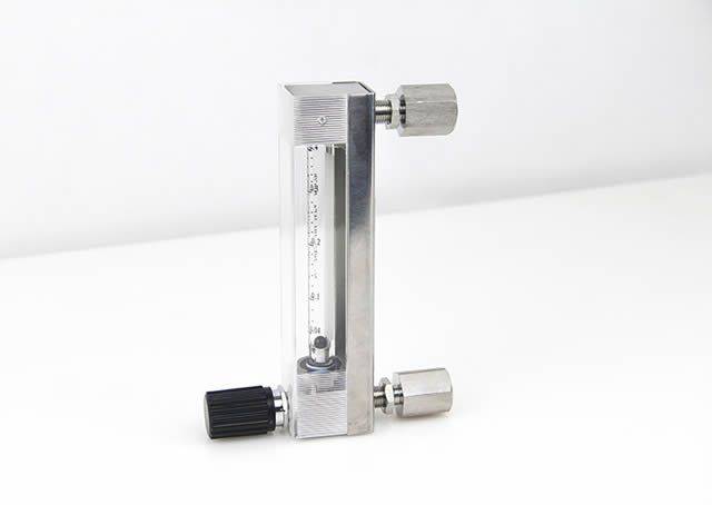
The rotor flow meter consists of a vertically placed cone tube and a rotor (floating) placed inside the tube and able to move freely up and down. When measured from the lower to the upper flowing cone tube, the fluid produces an upward effect on the rotor, which consists mainly of two parts, partly due to the variation of the kinetic pressure caused by the increased flow rate during the loop gap between the flow of the fluid and the cone, and partly to the flow of the fluid to the rotor. At the same time, the rotor itself is gravitational and downward. When fluid flows are smaller, the upward effect is less than the gravitational force of the rotor, and the rotor is in a lower position; as the flow increases, so does the upward effect, the rotor stabilizes at a certain altitude when the upward effect is balanced with the rotor gravity. The larger the flow, the higher the position of the rotor balance。
Resuscitation
When the rotor is in different positions in the cone tube, the circulation area between the rotor and the cone tube changes. According to the throttle method, within a given flow range, the flow rate of fluid flow in the loop gap is proportional to the flow. Since cone tubes have a fixed cone, the rotor's height is one-on-one with the circulation area. By measuring the height of the rotor in a cone tube, the flow size of the fluid can be measured indirectly。
In practical applications, the corresponding flow values are usually marked on the cone tube to read directly the scale values of the rotor. For some rotor flow meters with telecommunications output functions, transient position signals, such as current or pulse signals of 4-20ma, can also be converted to telecommunications through sensors for remote display, control and data processing。