I. Working principles for metal rotor flow meters
The metallic tube rotor flow meter floats in the measuring tube, which moves up as the flow changes, balancing the floating power of the float at a given position with the floating gravity. At this point, the circulation gap between the float and the plate (or cone tube) is maintained. The circumference area is proportional to the upward height of the float, i. E. The position where the float rises in the measuring tube represents the size of the flow, and the position of the variable float is transmitted from the internal magnet to the external indicator, so that the indicator correctly indicates the flow value at this time. This leads to a lack of direct contact with the measuring tube in the case of the indicator, so that, even when a limit switch or a transformer is installed, the instrument can be used for high temperature and high pressure working conditions。
Ii. Main characteristics and structural types of metal rotor flow meters
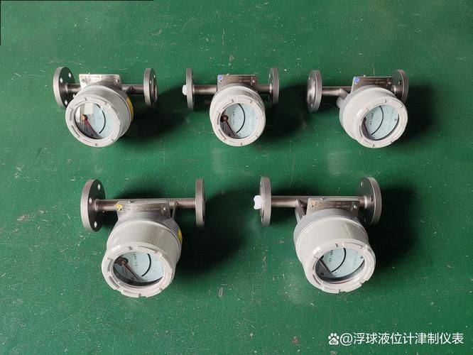
Total metal structure with indicator type, teleportation type, perishable type, high pressure type, condom type, blast resistance type. Standard analogue signal output and on-site instructions with 0-10ma, 4-20ma. Cumulative, digital communications, on-site modification of measurement parameters, different power mode functions, with magnetic filters and special specifications. It is widely applied in petroleum, chemical, power generation, pharmaceuticals, food, water treatment, etc. Complex, adverse environmental conditions, and flow measurement of various media conditions。
2. 1 main features
(1) strong, concise and reliable, with small maintenance and long life。
(2) modular, intelligent, indicator design。
(3) the requirement for the downstream straight section is low。
(4) there is a wider volume range of 10:1。
(5) short trip, small structural design。
(6) soft output through hart, showing instantaneous and cumulative flows, switch signal output, on-site setting and adjustment of media parameters, and off-site compensation。
(7) medium viscosity, density, temperature, pressure multilevel correction。
(8) multiple forms of in situ, remote, condomic, blast-proof, perishable, sanitary
(9) select stainless steel, haze alloy, titanium, ptfe material measurement system
(10) low pressure loss design。
(12) vertical, horizontal, various types of installation are more suitable for different uses
(13) whole metal structure suitable for high temperature, high pressure and corrosive media。
(14) available in flammable, explosive hazard settings
2. 2 structure type
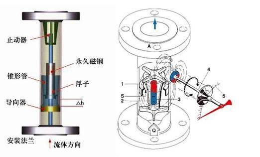
The flow detection element of the metallic rotor flow meter consists of a vertical cone tube that expands from the bottom up and a group of floats that move up and down the cone axis. When the hydrometeor is measured from the bottom up through the ring formed by the cone and floats, the upper and lower edge of the float produces a differential pressure to form the upward strength of the float, and the float rises when its upward strength is greater than the weight of the float immersed in the fluid, the area increases, the current speed of the circumference drops immediately, the upper and lower pressure of the float decreases, and the upward strength of the float is reduced, and the float stabilizes at a certain altitude until its upward strength equals the weight of the float in the fluid. Floats are at a high level in a cone and pass through traffic。
Various forms of installation, such as vertical or horizontal installation, can be performed according to the measured environment, as shown in the table below。
(1) high temperature structure
The high temperature structure type is the flow measurement of the medium used for the excessive temperature of the medium that requires thermal insulation measures for the measuring tube. High-temperature structures increase the distance between the measuring tube and the indicator to increase dispersion, increase the thickness of the insulation material and ensure that the indicator works within the permitted ambient temperature. In situ metallic tube rotor flow meters can measure the flow of media at temperatures of up to 400°c. (2) the structural blocker structure with a barrier device is used to measure the flow of the medium when the flow (pressure) factor is unstable, especially for gases. (3) package structure is used to measure the flow of media requiring heat or cooling (e. G., high viscosity and crystals). Low boiling point, low condensation point fluids are not accommodated or crystallized by heating or cooling media in the clamp. The import and export connection of the accompanying thermal medium, with a standard model of frf hg20594-97dn15pn1. 6, and other french specification links can be marked with a production plant with a pressure level of 1. 6 mpa.
2. 3 type selection
The rotor flow meter is primarily used to measure single-phase liquids or gases, which are not normally applicable when they contain particulate solids or liquid droplets in gases. Because floats are attached to the flow of particles or small bubbles that influence the measurements。
If a remote transmission signal is required to aggregate or flow control, a metallic rotor flow meter from the remote transfer is generally selected. In the case of an ambient atmosphere with blast-proof requirements and a gas source for the control instrument at the site, preference is given to the remote metal float meter, which, if selected, must be explosive-proof。
The choice of metal rotor flow meters is more common when measuring non-transparent liquids. For high viscosity liquids measured at temperatures higher than ambient temperatures and for liquids that are tempered to detect crystallization or condensation, a metallic rotor flow meter with a clamp should be selected。
Iii. Equipment notes
3. 1 direction of installation
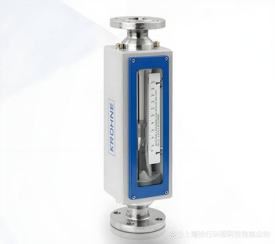
The vast majority of the rotor flow meters must be vertically installed on a non-vibration-free conduit, without a visible tilt, and fluids should flow down and up. And is more vertical than 2°, and horizontal angles are better than 2° when installed. The instrument does not require a strict upstream direct tube length, but there is also a 5d length requirement for manufacturing plants, which is not actually necessary。
3. 2 installation for impurities media
Magnetic filters should be installed if the medium contains an iron magnetic substance; if the medium contains solid impurities, consideration should be given to adding filters between valves and the direct section
3. 3 installation of pulse flow
The pulse of the flow itself, such as an outward repump or control valve at the intended instrument location, or a heavy load change downstream, should be replaced by a measurement position or remediate improvements to the plumbing system, such as a buffer tank, or, in the case of the instrument's own oscillation, such as the low gas pressure at the time of measurement, the incomplete opening of the upper instrument valve, and the failure of the control valve to be downstream of the instrument, should be overcome by targeted modifications or the selection of a device with a barrier。
3. 4 measurement of gas media
When used for gas measurements, the pressure loss of pipelines should be guaranteed not less than five-fold flow meters in order to stabilize the floats; if the gas is directly released into the atmosphere at the export of the flow meters, the valves should be installed at the export of the instrument, otherwise there would be a pressure drop at the floats that would cause the data to be distorted。
3. 5 conversion of field media parameters to standard flow at the time of marking。
Because the metal rotor flow meter used as a flow measurement is generally based on the media parameters provided by the user at the site, the calculation was selected and produced. Because there are some gaps in the media and the environment at each site, there are generally no standard tables, but they are based on the parameters of each site. Liquid instrumentation is usually water-marked to flow, gas instrumentation is air-marked to value in standard engineering states. When the fluid density of the conditions of use, the gas pressure temperature and the marking are inconsistent, the necessary conversions shall be made. Conversion formulae and methods are based on specifications of manufacturing plants。