Ab-class work details
There is no doubt that there are obvious advantages to the sound of a(a) and b(b), and i will speak from their rationale。
Transistor power amplifiers are made of triodes, which are structured in groups n-p, n-p
This n-p knot, which is closed when no additional voltage has been added (closed), only begins to operate if it is accompanied by a bias voltage and is above its door limit (silon tubes are 0. 6v, gill tubes 0. 2v), which is the n-p node that leads (opens) through the current. Category b working status is the non-addition of a fixed bias voltage, which is opened by a signal voltage, so that when the signal voltage is less than 0. 6 v (as in the case of silicon tubes), the triode is closed and the output is zero. Signal output only occurs at the end of a triode when the signal voltage is greater than or equal to 0. 6 v. It is clear here that the small signal voltage has been corrupted, and that on the output wave map, it is a small fraction of a straight line with the x-axis, and therefore different from the input wave shape, which is the result of a distortion, which is called the greater the distortion of the intersection and the more small signals are entered and the greater the distortion. In hearing, there is a loss of music detail, a blurry, weak letter, a discoherence of the whole music, not to talk about instrument quality, music. This is the working state of the type b amplifiers。
Plus, b power magnification must be made of two transistors, with a tube working on a signal
The other works for the negative half-week of the signal voltage, and the other one works as a conduit, and the other is in a cut-off state, when the other half-week of the signal voltage arrives in a state of exchange, which naturally leads to a distortion. The lack of a cut-off effect on the anti-electric dynamics of loudspeakers and the feedback of anti-electric dynamics even to the front-level amplifier circuits has led to a sharp increase in internal resistance, a deterioration or even loss of the nitric coefficient of entry, so that it is felt that the anti-electric dynamics of loudspeakers are not well controlled, the sound is distasteful and the thrust is inadequate。
But there's also the advantage of a b-class system, which is efficient and can reach more than 75%, so it can
The use of smaller power tubes to produce larger power and the push of electrical circuits have an effect on the suppression of occasional waves to reduce non-linear distortions. The disadvantage designer for type b power is adding to the input plate of the tripolar tube a preset, slightly smaller than the fixed voltage of the primary voltage, making the tripolar tube slightly more than zero at static output level, enabling the tripolar tube to operate at very small signal voltages, having current output, making the transistor more than half a cycle of conductivity, making it non-existent, that is, ab, whereas in actual use, it is now rarely used in category b, and most are in category a, which overcomes the problem of type b power discharge, and is much more efficient than category a, and now uses the audio to release it in order to improve the sound, tends to tilt the electrical pressure above the door limit, leaving the transistor in a state of operation close to category a. That's what's known as the high optimal ab category。
Category a is where the positive bias is set at half the maximum output power, so that the power is placed without signal input
It is also in a state of full load operation, which allows for current output throughout the signal cycle. The a-type applications keep the triodes in linear areas, so the a-type applications are almost non-false and have a particularly good sense of sound quality, especially when small signals, the whole sound is balanced, lubricated and well-coordinated。
But there are also shortcomings in type a power release, first and foremost inefficient, usually not more than 25%, and large amounts of electricity turn to heat
In the same power, power supply is often much larger than that of ab. And because of the high current of work, the a is the main power source at the same output
It is much lower, so its output peak voltage is limited and its input voltage is limited by the amplification factor of the output voltage. As a result, the great dynamic of music is affected。
Ab-type credits application
Combined application is one of the ab-type applications, as shown in figure 1. Ics are linked to improve output currents, increase carrying capacity and carry lower resistance to horn loads. In order to prevent discrepancies between the output currents of the two amplifiers, a small electrical resistance is combined at the end of the output as a mean pressure and flow. The bridge mode is applied at the same power voltage, with the output pressure of the bridge doubling and the output power being four times that of a single-end mode. Figure 2 shows the application of circuits to the lm 3886 bridge。
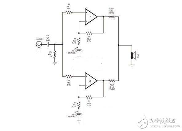
Figure 1
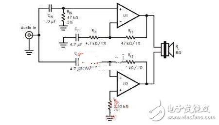
Figure 2
Stability
The stability of design applications is important and imperfect design can cause shock. There are many reasons for oscillation. One of the most common oscillations is that the negative half-week of the wave shape produces “fuzz”. The oscillation is not only in negative half-weeks, and every single point on the sine wave is possible。
Three types of shock solution are generally available, the first being the method of adding buffers to the rc defusing circuit (also known as the zobel migration network) at the output end; the second is the amplifier gain method, with most ab-type job placements requiring a closed circle gain of more than 10 times, adding feedback caps to feedback circuits and increasing circuit stability; the third is to improve the power supply by installing high-frequency filtering caps in close proximity to the device。
Heating factor
All ic products are subject to heat depletion and ab-type work is operated with greater heat generation. It depends on power voltage and output loads (8 or 4 times)。
The dispersive effects depend on the heat resistance that the ic itself encapsulates. θja means "thermal resistance of the knot and the environment" and θjc means "thermal resistance of the knot and the shell". It is also a heat retardation in °c/w, and it refers to “thermal retardation of the outer shell and the radiator” and to “thermal retardation of the dispersion of the environment”。
Pd max = v2/(2x2rload)+pq
Of these, v is power voltage and pq is static。
Mm1875 pdmax value
Pdmax = (50 x 50) / (2 x (3. 14) 2 x 8) + (50 v x 70 ma)
Pdmax = 15. 35 + 3. 5 = 18. 85 w
Most of the ic data manuals have the corresponding “utilisation” curve, which is the simplest way to find pdmax values. Not all working conditions can be found in the curve, but there is a need to ensure that the horn load corresponds to the selected “work” curve, as shown in figure 3。
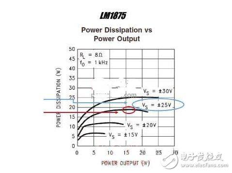
Figure 3 lm 1875 working curve
For the calculation of the temperature of the device, the total heat resistance of the chip is calculated first, assuming a heat resistance of 2°c/w of the dispersed heat table。
Lf1875 (θjc+heat retardator) = (3°c/w+2°c/w) = 5°c/w
Considering that the maximum tolerance temperature of the chip does not exceed 150°c, if the maximum ambient temperature is 50°c, the maximum potential temperature of the chip can be calculated。
(total heat retardation) x pdmax+t (maximum ambient temperature) = (5°c/w) x (18. 85°w)+50°c = 144°c
A simple and easy way to identify the size of the dispersing film is shown in figure 4. First, the corresponding pdmax values are found on the vertical axis, then the maximum ambient temperature is determined on the trans-axis, and the appropriate radiator heat retardation is selected, where all the lines intersect at 150°c, i. E. The maximum tolerance of the ic。
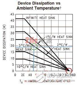
Figure 4
Pcb line
The line is designed with regard to currents between the lines. From the point of output to the point of source of power, it is a high current, and the width of the entry and output lines is already large, although resistance still exists. The currents between the lines produce a mixed waveform。
The skeletal shape is created by the direct connection of the input signal to the output signal. The output signals now vary from the input to the power flow from the output to the input. This will add a mixed signal to the input signal end of the amplifier。
The line before and after the modification is shown in figure 5. The input and output lines are now separated and the two lines are connected at more stable geo-lined points (the point of connection of the power filter capacity)。