Role and components of circuits
The circuits are current circuits, which are for some purpose which need to be combined in a certain way by certain electrical equipment or metaware。
The structure of the circuits and the tasks that can be accomplished are varied。
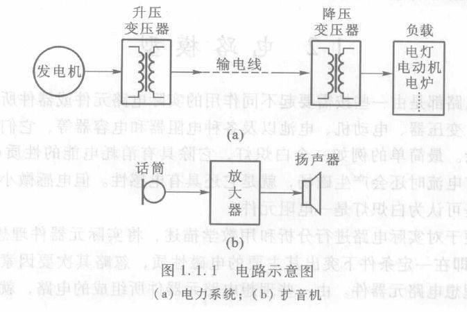
The most typical example is the power system, whose function is to achieve the transmission and conversion of electricity, which consists of three components: power supply, load and intermediate。
Another function of circuits is the transmission and processing of signals, common examples being megaphones, where language or music (often called information) is first converted from microphones to corresponding voltage and currents, which are telecommunications numbers. It was then transmitted via a circuit to the speaker and returned to language or music. As the telephonic number of the microphone output is weak and insufficient to drive the speaker's pronunciation, amplifier amplifiers are used to magnify it. This conversion and magnification of the signal is called signal processing。
A microphone is a device for the output of a signal, referred to as a signal source, which corresponds to a power source, but unlike a generator, a battery, as described above, the pattern of telecommunications numbers (voltage and current) for the output of a signal depends on the information added. The speaker is a device for receiving and converting signals, i. E. A load。
There are many examples of signal processing and transmission, such as radios and televisions, whose receiving antennas (sign sources) convert the electromagnetic waves containing language, music, image information to the corresponding telecommunications numbers, and then transmit and process the signals via circuits (modification, frequency, wave detection, magnification, etc.) to loudspeakers and cathodes (loading) and restore the original information。
Whether the transmission and conversion of electrical energy, or the transmission and processing of signals, where the voltage or current of the power or the signal source is referred to as incentive, it drives the circuit; it is referred to as response by the voltage and current generated by the incentive in the various parts of the circuit. The so-called circuit analysis is to discuss the relationship between circuit incentives and response under the conditions of known circuit structure and metrware parameters。
Circuit model
The actual circuits consist of physical circuit elements or devices that function as needed, such as generators, transformers, electric motors, batteries and various types of resisters and capacitors, which are more complex in their electromagnetic properties. The simplest example, for example, is a incandescent lamp, which, in addition to its energy-consuming nature (electrical resistance), produces magnetic fields when electrical currents become available, i. E., it is electric. However, the electrons are small and negligible, so that incandescent lamps can be considered a resistance element。
In order to facilitate the analysis and mathematical description of the actual circuits, the actual metaware is idealized (or modelled) to highlight its main electromagnetic properties under certain conditions, neglecting its secondary elements and treating it as close to an ideal circuitary device. The circuits made up of ideal electrons are the circuit models of the actual circuits, which are scientific abstractions and generalizations of the electromagnetic properties of the actual circuits. Among the ideal circuitary devices (the future ideal is not written) are electrical resistance elements, sensory elements, capacitive elements and power units. These metaware are shown by the respective parameters。
For example, commonly used flashlights, whose physical circuit unit consists of dry batteries, beads, switches and connector lines, are modelled as follows:
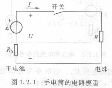
The beads are electrical resistance elements with parameters r and dry batteries with parameters e and internal resistance (known as r0), which connect the middle link between the dry cell and the beads (which also includes switches) and which are ignored as an ideal conductor without electrical resistance。
Future analyses refer to circuit models, short of circuit maps. In the circuit chart, the various elements are represented by the specified graphic symbol。
Reference direction for voltage and currents
The above figure is the simplest straight current electrical resistance circuit, of which e, u, r0 are power power, end voltage and internal resistance, respectively, and r is load resistance. When it's off, there's electricity on the circuit i. Electricity flow i, voltage u and dynamic e are the basic physical mass of the circuit, and when analysing the circuit, they must be marked by arrows or +s on the circuit map to indicate their direction or polarity (as shown in the figure) in order to correctly list the circuit equation。
With regard to the direction of voltage and currents, there is a difference between the actual direction and the reference direction。
It is customary to specify the direction of the positive or negative charge movement as the direction of the current (actual direction). The direction of currents is objective, but when analysing more complex straight currents, it is often difficult to prejudge the actual direction of currents in a given route; for communication, the direction changes over time, and it is not possible to indicate its actual direction on the circuit map with an arrow. For this reason, when analysing and calculating circuits, it is often possible to select a particular direction as a reference direction for currents or as a positive direction。
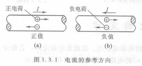
The chosen current reference direction does not necessarily correspond to the actual direction of the current. The current is positive when the actual direction corresponds to its reference direction, whereas the current is negative when the actual direction is inconsistent with its reference direction。
Therefore, the current value is given a positive or negative score only after the reference direction is selected。
The voltage and the electric dynamics are markers, but when analysing the circuits, they are said to have direction, as is the current。
The direction of the voltage is defined as the high level (+ polarity) end pointing to the low level (-polarity) end, i. E. The direction in which the level is reduced。
The direction of the power dynamic is defined as the direction of the rise of the power level within the power source from the low (-polar) to the high (+ polar) end。
The direction of currents, voltages and motors indicated on the circuit map is generally a reference direction, whether they are positive or negative, depending on the reference direction selected。
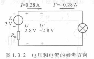
The reference direction for voltage u corresponds to the actual direction and is therefore positive, while the reference direction for u's is contrary to the actual direction and therefore negative. Both can be written as u =-u'; so can electricity, i =-i'。
The reference direction of the voltage, in addition to being expressed in polar +, -, can also be used as a double subscript. For example, a, b voltage between points uab, which is referred to by a point pointing to b, which means that the reference polarity of a point is +, the reference polarity of b points is -. Uba, uab = -uba if reference orientation is b pointing to a. The current reference orientation can also be expressed by double subscripts。
Our statutory units of measurement are based on the international system of units (si)。
In the international unit system, the current is in amber (a). The current is 1a when the charge in 1s (sec) cross-section through the conductor is 1c (kulen). Small currents are measured in milligrams (ma) or microan (ua). 1ma = 10-3a, 1ua = 10-6a。
In the international unit system, volts (v) are the units of voltage, which is 1v when the power of the field moves the charge of 1c from one point to another by 1j (jour). Microvoltage is measured in milliv (mv) or microvolt (uv) and high voltage is measured in kv。
The units of electric motion are the same as the volts。
Om law
This is the om law。
It's one of the basic laws for analysing circuits。
U / i = r
It is known from the above that when the voltage is added to u, the greater the resistance r, the smaller the current. It is clear that electrical resistance has a physical character that hinders the flow of electricity。
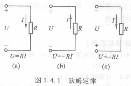
U = ri
U = -ri
In the international unit system, the unit of resistance is om. When the electrical voltage at both ends of the circuit is 1v and the current passed is 1a, the electrical resistance of the circuit is 1 in the same section. High resistance is measured in thousands of euros (k) or mega-eu (m)。
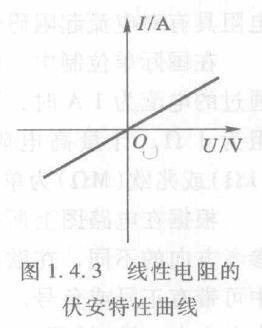
The electrical resistance, which follows the om law, is referred to as linear electrical resistance, which is a constant that expresses the circuit properties of the paragraph and is not related to voltage and current. The above figure is commonly referred to as the curve of linear electrical resistance。
Power is loaded, open and short circuit
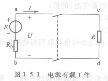
Close the switch in the top chart and connect the power to the load, which is the power load。
Electricity and currents
Using om's law, you can list the currents in the circuit
I = e / (r + r0)
And the voltage at both ends of the load resistance
U = ri
Finally
U = e-ir0
Thus, the power-end voltage is smaller than the electric motion, and the difference is that the current is reduced by the voltage generated by internal resistance from the power source. The greater the current, the more the power end voltage falls。
A curve indicating the relationship between power source voltage u and output current i, known as the external characteristics of the power source。
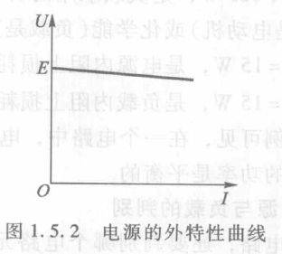
The slopes are related to the internal resistance of the power supply. The power supply is usually small when r0