Three-phase communication is a frequent feature of life and requires three-phase transmission in a given environment due to the load of high-power electrical equipment, which is a form of transmission of electricity, abbreviated as three-phase transmission. Three-phase communication power is a power source consisting of three communication power at the same frequency, with equal amplitudes, and with a hierarchical variation of 120°。
Characteristics of tri-phased electricity
There's a line of fire between one and three, and there's no touch of that one. There's 380 v between the two, and there's 220 v between each and zero, which is what we use daily。
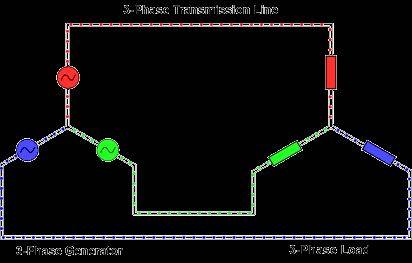
Two, three-phase electrics can be connected to the electric generator, three of which enters the electric generator at the same time, with a star and triangle。
3 any two voltages are 380 v instead of 220 v。
It can be used to make up 220 v with one of the zero lines。
5. The neutral line is generally used to channel an imbalanced current when the triple load is unbalanced。
The zero line is a circuit from the neutral point of the transformer, which is powered by the electrical equipment in retrospect with the trajectorial circuit, and, normally, the zero line repeats the surface at the neutral point of the transformer, with the double protected voltage being the difference between the two points and the line being the equivalent of the reference point of the circuit。
Mathematical formula for three-way communication of voltage
V1 = asin (2ft) = asin (wt)
V2 = asin (2 ft - 2 g) = asin (wt - 2 g)
V3 = asin (2 ft + 2 g) = asin (wt + 2 g)
Of these, a is the peak of voltage, and f is the frequency of voltage exchange。
Distinction between three and two
The difference between three- and two-phase electricity is that three-phase electricity is two more fire wires than two-phase electricity, and that the three-phase electricity is of a different grade, with three-phase electricity being 380 v, two-phase electricity being 220 v, three-phase electricity being used to supply electricity to enterprises and factories, for example, large equipment such as electrics, pumps, etc., and more for the use of household appliances, single-phase electricity, two-phase electricity, three-phase electricity being the name of the three-phase four power system (380 v/220 v). The single-phase is a neutral line (zero line) and any line (a, b, c) with a voltage of 220 v. Both indicate that any two-phase line (ac, ab, bc) consists of a voltage of 380 v. A three-phase (a, b, c) line, 3 Φ380 v, indicating a 120 degree difference. For electrical loads, there are two relays (stars and triangles) of the three phases。
Distinction between three-phase electricity and one-phase electricity
Distinction between three-phase and single-phase electricity: a single phase is 220 v, which is an inter-line-to-zero voltage. The third is the inter-phase voltage of 380 v between a. B. C., which is used as an electrical power or equipment for 3-phase 380 v. Generators generate three-phase power sources, each of which, with its inter-point, can constitute a single circuit to provide power to users. Note that the communication circuit cannot be called a positive or negative pole, but should be called a phase line (fire line in civilian electricity) and a neutral line (zero line in civilian electricity)。
Three-phase electrical principles
The three-phase electricity principle is interpreted in one example, although it is shallow, symmetrical and quick to understand。
The three men stood on the three vertebrates of a positive triangle, and the a side pushed first, followed by the b side, followed by the c side, in turn, and the wheel kept moving. If someone uses more force, the three sides are unbalanced, the support points shake, the support points are counterproductive. The neutral point (n-line) has electricity passing], and if the wheel is not holding back, there will be a drive-by phenomenon, which will be tantamount to a short-circuit phenomenon, as is the case for three-phase electricity。
Three circuits
The three are generally telecommunications, with phase deviations, and currents automatically move from high voltage to low pressure. For example, when welders are attached to one or two of the three, this is called u, v si, 380v, and at some point when u is high voltage, v si, is low voltage, so that there is a gap between high and low voltage, there is a current passing through and a circuit. Of course there are times when we're high
E. D. Three-phase power
Each waveform of the triangulation is a single chord, but each angle varies 120 degrees. The three electricitys are the minimum phase in which a fixed start-up rectangular in direction can be generated in the electric rotor。
Three-phase tethering
The three phase electricitys consist of three ac voltages of the same frequency and of similar magnitude. Each ac volt "phase" is 120° away from another ac voltage (figure 1). This can be graphically expressed using wave and vector maps (figure 2)。
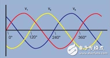
Figure 1. Three-phase voltage waveform
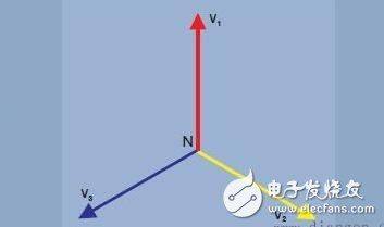
Figure 2. Three-phase voltage vectors
There are two reasons for using the three-phase system:
1. A rotating magnetic field may be created in motors using a voltage of three vector intervals. This allows motors to be activated without the need for additional bypass groups。
The three-phased system can be connected to the load, and the required number of copper cables connected (transmission losses) is half of the other method。
Let's look at three single-phase systems, each providing a load of 100 w (figure 3). The total load is 3 x 100 w = 300 w. To provide electricity,1 the ampere current runs through six lines, resulting in losses in six units. Three power sources could also be connected to a public return, as shown in figure 4. The load is considered to be balanced when each stage has the same load current. When the load is balanced and the three current phase shifts 120° to each other, the sum of the current at any point is zero and there is no current on the return circuit。
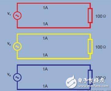
Figure 3. Three single-phase power sources - 6 unit losses
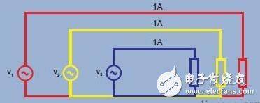
Figure 4. Three-phase power source, balanced load - 3 unit losses
Three lines are required to transmit power in a three-way 120° system, while six lines are required in other ways. The number of copper cables required has been reduced by half and the loss of lead lines will be halved。
Y-shaped or star-shaped
Three-phase systems with a public connection are commonly referred to as “y-shaped or star-shaped” transpositions, as illustrated in figure 5。
Public points are called neutral points. For safety reasons, this point is usually connected to the power source. In practice, loads are not perfectly balanced and are transmitted using the fourth “neutral” line. If permitted by local regulations and standards, a neutral conductor may be much smaller than the three dominant ones。
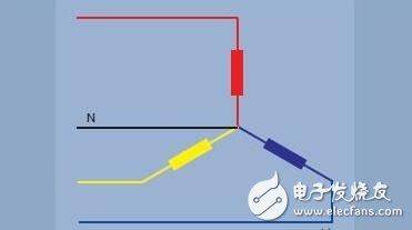
Figure 5. Y-shaped or asterisk-triple line
Triangulation
The three single-phase power sources discussed above can also be linked. At any given point in time, the sum of three 120o phase voltages is zero. If it is zero, both end points are at the same level of electricity and can be connected together. This method of succession, as illustrated by the graph in figure 7, is expressed in greek letters, known as the triangle method。
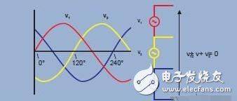
Figure 6
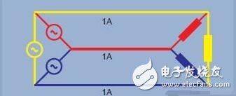
Figure 7. Triangulation - 3+3
Y-form and triangle
The y-forming method is used to supply electricity for daily single-phase equipment used in homes and offices. A single load is connected to a y-shaped leg between the line and the neutral line. The total load of each phase is shared as much as possible to provide a balanced load for the main three-phase power source. Www. Diangon. Com
Y-forming can also provide single- or three-phase electricity for higher power loads at higher voltage. Single-phase voltage is the phase to neutral. Higher inter-phase voltage is also available, as shown in the black vector in figure 8。
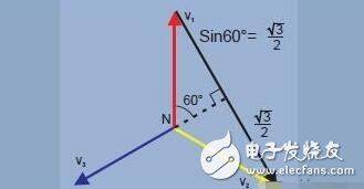
Figure 8 v case-case = √3 x v case-neutral
Triangulation is most commonly used to supply electricity to the high power tri-phase industries. However, different voltage combinations can be obtained from tri-triangular power sources by connecting or "connecting " along transformer wires. In the united states, for example, the 240v triangle system can have a split or central split loop, providing two 120v power sources (figure 9). For safety reasons, the central interface can be placed on the transformer. A further 208 v voltage was provided between the centre and the third “high foot” of the triangle。
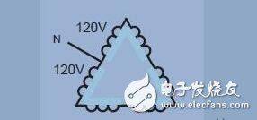
Figure 9. Triangulation method, using "segregation" or "centre separation" loops
Power measurement
In communication systems, power is measured using power meters. Modern digital sample power tables, multiplying the instant spot of multiple voltage and currents, calculate instant power and then take an average of instant power over a cycle to indicate power. The power scale will be measured accurately in a wide range of waveforms, frequencies and power factors, with regard to power availability, visual power, no load, power factor, harmonization, etc. In order for the power analyser to provide good results, the wiring configuration must be correctly identified and the power analyser linked correctly。
Single power table connection
Only one power table is required, as shown in figure 10. The connection between the system and the power gauge and current terminals is simple and simple. The voltage end of the power table is connected by load, and the current is fed by the current end of the load。
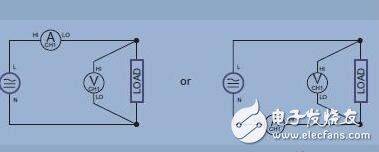
Figure 10. Double single-stage and dc measurements
Three-way connection
In this system, all voltage is generated from a central transformer wire, as shown in figure 11. This is common in residential applications in north america, where a 240-v power supply and two 120-v power sources may vary in loads per leg line. To measure total power and other quantities, two power tables should be connected, as shown in figure 11。
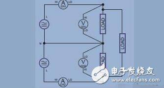
Figure 11. Single line
Blondel theorem: required number of power tables
In the single-phase system, there are only two lines. Power is measured using a power gauge. In the three-line system, two power tables are required, as shown in figure 12。
In general, the required number of power tables = lines - 1
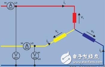
Figure 12. Three-line y-shaped system
Validate the tri-y system
The instantaneous power measured by the power gauge is the sum of instantaneous voltage and current samples。
Power table 1 read = i1 (v1 - v3)
Power table 2 reading = i2 (v2 - v3)
W1 + w2 = i1v1 - i1v3 + i2v2 - i2v3
= i1v1 + i2v2 - (i1 + i2) v3
(i1 + i2 + i3 = 0, so i1 + i2 = -i3)
2 readings w1 + w2 = i1v1 + i2v2 + i3v3 = total instant power。
- two power gauges
When there are three lines, two power meters are required to measure total power. A voltage end that connects two phases to the power table according to the method shown in the figure。
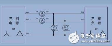
Figure 13. Three-phase, two power gauge methods
Three-by-three-by-three
As noted earlier, while measuring total power in a three-line system requires only two power scales, it is sometimes easy to use three power scales. In the relay as shown in the figure, a false neutral line is created by connecting the low voltage end of all three power meters。
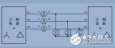
Figure 14. Three-to-three (three power gauge methods, three-to-four mode of analyser)
The advantage of the three power scales of the three lines is that they indicate the power of each phase (which is not possible in the two power scales) and the medium-line voltage。
Three-by-three
The measurement of total power in a four-line system requires three power meters. The measured voltage is the real photovoltage. By using vector mathematics, inter-phase voltage can be accurately calculated from the range and phase of the phase. The modern power analyser also uses the law of kirhol to calculate currents passing through the median line。
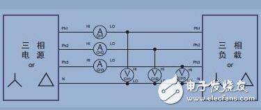
Figure 15. Three-phase four (three power gauge methods)