While single-phase electricity is used to provide electricity for civilian and office appliances, the three-phase communication systems are used extensively for distribution and for the direct provision of electricity for higher-capacity equipment。
Three-phase system
The three phase electricitys consist of three ac voltages of the same frequency and of similar magnitude. Each ac volt "phase" is 120° away from another ac voltage (figure 1). This can be graphically expressed using wave and vector maps (figure 2)。
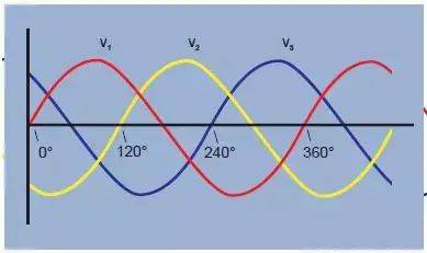
Figure 1. Three-phase voltage waveform
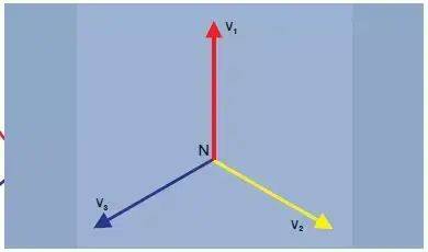
Figure 2. Three-phase voltage vectors
There are two reasons for using the three-phase system:
1. A rotating magnetic field may be created in motors using a voltage of three vector intervals. This allows motors to be activated without the need for additional bypass groups。
The three-phased system can be connected to the load, and the required number of copper cables connected (transmission losses) is half of the other method。
Let's look at three single-phase systems, each providing a load of 100 w (figure 3). The total load is 3 x 100 w = 300 w. To provide electricity,1 the ampere current runs through six lines, resulting in losses in six units. Three power sources can also be connected to a public return, as shown (figure 4). The load is considered to be balanced when each stage has the same load current. When the load is balanced and the three current phase shifts 120° to each other, the sum of the current at any point is zero and there is no current on the return circuit。
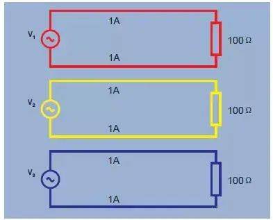
Figure 3. Three single-phase power sources - 6 unit losses
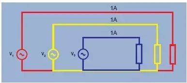
Figure 4. Three-phase power source, balanced load - 3 unit losses
Y-shaped or star-shaped
Three lines are required to transmit power in a three-way 120° system, while six lines are required in other ways. The number of copper cables required has been reduced by half and the loss of lead lines will be halved。
Three-phase systems with public connections are commonly referred to as “y-shaped or star-shaped” transpositions, as illustrated by the graph (figure 5)。
Public points are called neutral points. For safety reasons, this point is usually connected to the power source. In practice, loads are not perfectly balanced and are transmitted using the fourth “neutral” line. If permitted by local regulations and standards, a neutral conductor may be much smaller than the three dominant ones。
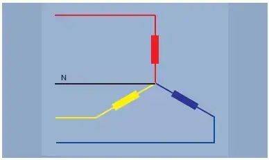
Figure 5. Y-shaped or asterisk-triple line
Y-shaped or star-shaped
The three single-phase power sources discussed above can also be linked. At any given point in time, the sum of three 120o phase voltages is zero. If it is zero, both end points are at the same level of electricity and can be connected together. As shown in the graph (figure 7), this sequence is expressed in greek letters and is called a triangle。
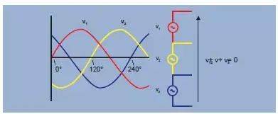
Figure 6
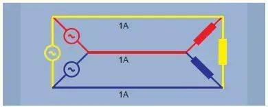
Figure 7. Triangulation - 3+3
Y-form and triangle
The y-forming method is used to supply electricity for daily single-phase equipment used in homes and offices. A single load is connected to a y-shaped leg between the line and the neutral line. The total load of each phase is shared as much as possible to provide a balanced load for the main three-phase power source。
Y-forming can also provide single- or three-phase electricity for higher power loads at higher voltage. Single-phase voltage is the phase to neutral. Higher inter-phase voltage is also provided, as shown in black vectors (figure 8)。
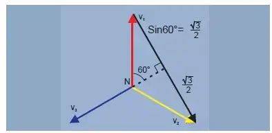
Figure 8 v case-case = √3 x v case-neutral
Triangulation is most commonly used to supply electricity to the high power tri-phase industries. However, different voltage combinations can be obtained from tri-triangular power sources by connecting or "connecting " along transformer wires. In the united states, for example, the 240v triangle system can have a split or central split loop, providing two 120v power sources (figure 9). For safety reasons, the central interface can be placed on the transformer. A further 208 v voltage was provided between the centre and the third “high foot” of the triangle。
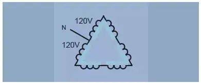
Figure 9. Triangulation method, using "segregation" or "centre separation" loops
Power measurement
Single power table connection
Only one power table is required, as shown (figure 10). The connection between the system and the power gauge and current terminals is simple and simple. The voltage end of the power table is connected by load, and the current is fed by the current end of the load。
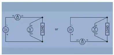
Figure 10. Double single-stage and dc measurements
Three-way connection
In this system, all voltage is generated from a central transformer wire, as shown in figure 11. This is common in residential applications in north america, where a 240-v power supply and two 120-v power sources may vary in loads per leg line. To measure total power and other quantities, two power tables should be connected, as shown (figure 11)。
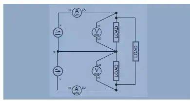
Figure 11. Single-phase 3
Blondel theorem: required number of power tables
In the single-phase system, there are only two lines. Power is measured using a power gauge. In a three-line system, two power meters are required。
In general, the required number of power tables = line-1
Validate the tri-y system
The instantaneous power measured by the power gauge is the sum of instantaneous voltage and current samples。
Power table 1 read = i1 (v1 - v3)
Power table 2 reading = i2 (v2 - v3)
W1 + w2 = i1v1 - i1v3 + i2v2 - i2v3
= i1v1 + i2v2 - (i1 + i2) v3
(i1 + i2 + i3 = 0, so i1 + i2 = -i3)
2 readings w1 + w2 = i1v1 + i2v2 + i3v3 = total instant power。
- two power gauges
When there are three lines, two power meters are required to measure total power. A voltage end that connects two phases to the power table according to the method shown in the figure。
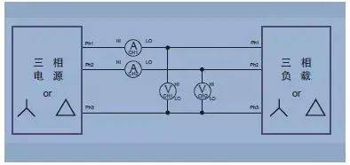
Figure 12. Three-phase, two power gauge methods
Three-by-three-by-three
As noted earlier, while measuring total power in a three-line system requires only two power scales, it is sometimes easy to use three power scales. In the relay as shown in the figure, a false neutral line is created by connecting the low voltage end of all three power meters。
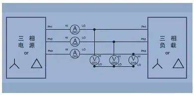
Figure 13. Three-to-three (three power gauge methods, three-to-four mode of analyser)
The advantage of the three power scales of the three lines is that they indicate the power of each phase (which is not possible in the two power scales) and the medium-line voltage。
Three-by-three
The measurement of total power in a four-line system requires three power meters. The measured voltage is the real photovoltage. By using vector mathematics, inter-phase voltage can be accurately calculated from the range and phase of the phase. The modern power analyser also uses the law of kirhol to calculate currents passing through the median line。
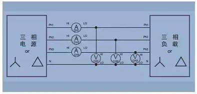
Figure 14. Three-phase four (three power gauge methods)
Configure measurement equipment
For a certain number of (n) online, n-1 power meters are required to measure the overall electrical mass, such as power. It is important to ensure that there are sufficient numbers of corridors and that they are properly connected。
The modern multi-channel power analyser will use the corresponding built-in formula to calculate the overall electrical mass directly, such as the watt, volt, amber, volam and power factors. The formula is selected on the basis of the wiring configuration, so the setting of the wiring is essential to obtain good overall power measurement. Power analysers with vector functions will also convert phase voltage (or y-shaped) fractions into linear voltage (or triangle) fractions. Only factor 3 can be used to achieve inter-system conversion or to determine the measurement of a single power table on the equilibrium linear system。
Knowledge of wiring and proper connectivity are essential for power measurement. Be familiar with the usual wiring system, remember the blondel theorem, which will help you get the corresponding connection and the results you can rely on。