The meaning of the trigger for the oscillator:
(b) capture of interested signals
Determines the wave shape at zero。
I. Rationale for oscilloscope triggers
The signal, as shown in figure 1, enters the oscilloscope through a probe and then the decayer amplifier is divided into two paths, one through adc and the other through the trigger matrix. The function of the trigger time base module is to monitor the incoming signal and determine whether the trigger condition is met. The trigger time-based module controls the start of the oscilloscope collection and the cessation of critical actions。
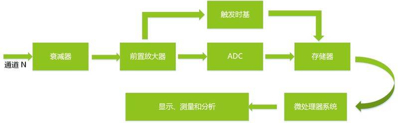
Figure 1 trigger of oscillators
If the oscillator does not have a trigger system, the waveform of the sample is superseded at intervals or at random intervals, so that the waveform seen on the screen is unstable due to uncertainty and irregularity of the sampling position. Figure 2 shows the waveforms of the swires captured by the oscillator when the trigger conditions are not met, and the collection of each sill is random, so the waveforms observed on the oscillator are volatile。
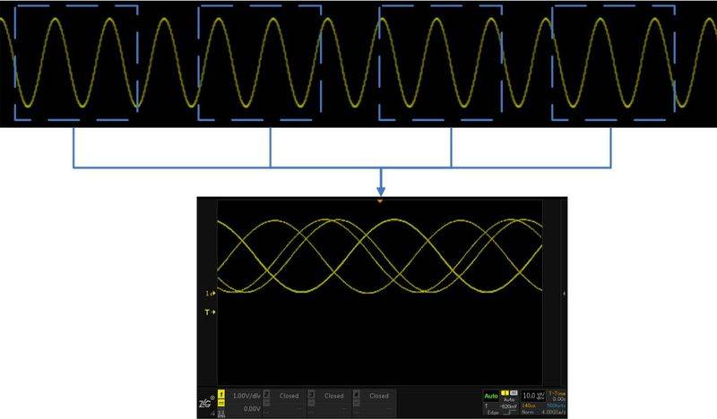
Figure 2
As shown in the following dynamic chart:
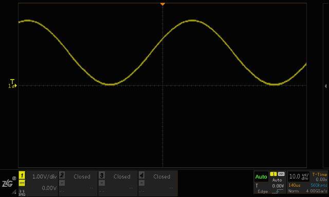
Figure 3
Figure 4 shows the wave shape observed on the oscilloscope at the steady trigger. At this point, since each trigger point occurs at the point where the signal is triggered by the electrical level, the trigger level is, in most cases, benchmarked by a direct current level, which is the starting point for the sample wave shape when the electrical pressure of the signal exceeds the direct current level. So the multiple waveforms captured on the screen have the same time frame, and the waveforms look stable。
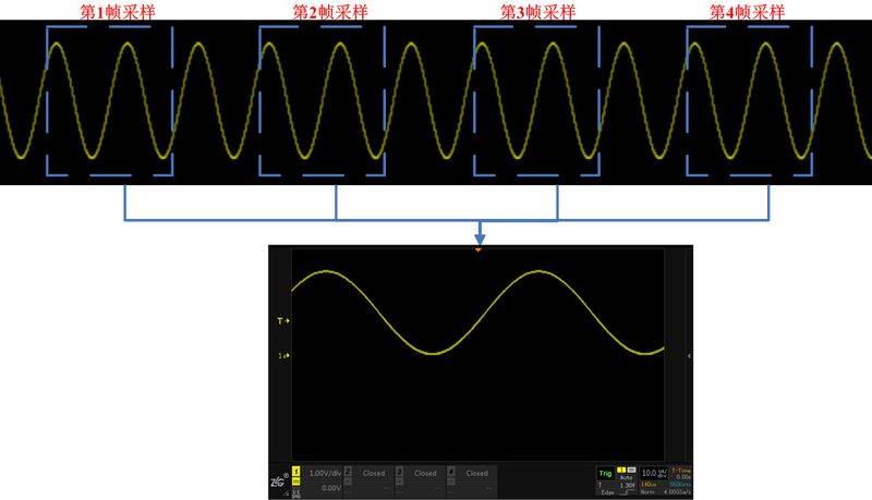
Figure 4 stabilization triggers
The dynamic changes are shown in figure 5 below:
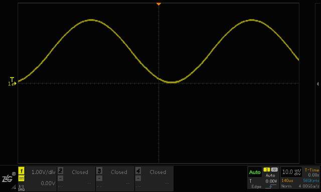
Figure 5
If engineers who had previously used simulated oscillators knew that their trigger mechanism was a signal scan and display after the trigger, the wave shape observed on the screen was after the trigger point. However, the trigger mechanism for a digital oscillator is that if the trigger condition is not met, the oscillator does not wait for collection, and the actual internal collection of data continues at full-speed caches. As shown in figure 6, and due to the limited depth of the oscillator storage, the cache will soon fill and recycle new data to cover old data. It continues to trigger events. So the internal storage of the oscillator is divided into two data, pre-trigger (pre-trigger) and post-trigger (post-trigger)。
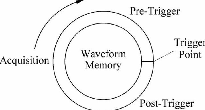
Figure 6 data before and after the trigger
So the waveforms that we now see in the digital oscillator are both pre-trigger data and post-trigger data, and can set the trigger point to adjust the rate of the pre-trigger and pre-firing waveforms, which is one of the advantages of the digital oscillator, as illustrated by the figure, which is a waveform along the edge of the digital oscillator that triggers collection. The trigger point is the zero point of the wave shape collected on the oscillator, the negative point of time before the trigger point and the positive point of time after the trigger point。
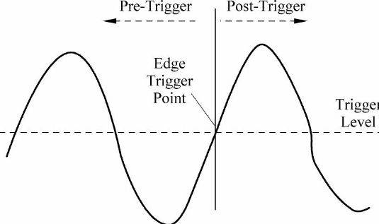
Figure 7 waves before and after triggers
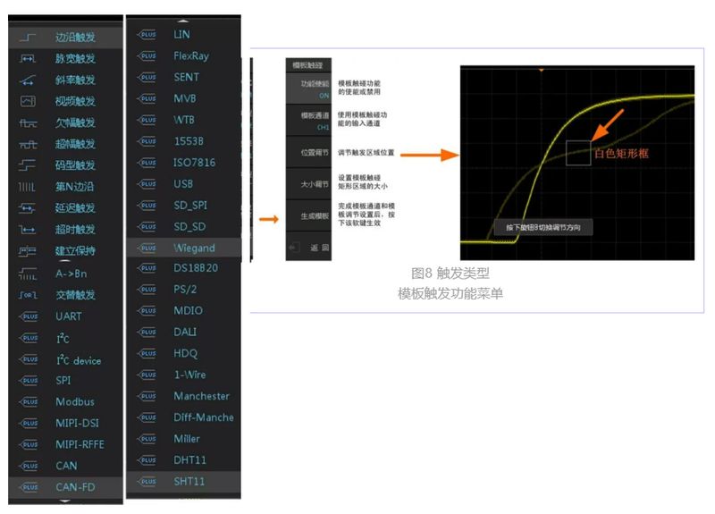
Type of oscillator trigger
Based on different applications, different trigger conditions will be used to set the signal characteristics expected to be captured, so the zds 5000/4000 is very rich in trigger conditions set in figure 8 and can be adapted to different application needs. It contains not only 13 basis triggers (marine, pulse, tilt, video, default, excess, code, n border, delay, time overtime, set-up, a-> bn, alternation), but also free support for more than 30 triggers。
Digital oscilloscopes have a relatively large dead zone time, but the zds series oscilloscope is marked with more than 40 trigger conditions, which greatly improve the efficiency of the operation, provided that the user can estimate roughly the signal characteristics that may be to be captured。