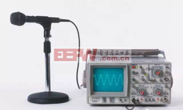
The oscilloscope is an electronic measuring instrument using electronic oscilloscopes to convert transversal telecommunications, which cannot be directly observed by human eyes, to images and display on fluorescent screens for measurement. It can use oscillators to observe wave-shaped curves of different signal ranges over time, and it can also be used to test different amounts of power, such as voltage, currents, frequencies, phase differentials, modulations, etc. It is an essential instrument for observing experimental phenomena in digital circuits, analysing problems in experiments and measuring results。
2. The principles of oscilloscope work - structural composition
Electronic oscilloscopes consist of four components: oscilloscopes, vertical deflection systems, horizontal deflection systems and power supply circuits。
(1) oscilloscope
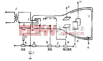
The cathode ray tube (crt) abbreviated wave tube is the core of the oscilloscope. It converts telecommunications to light signals. As shown in the figure below, the electronic gun, the deflection system and the fluorescent screen are sealed in a vacuum glass shell, forming a complete oscilloscope。
(2) vertical diversion system
Vertical deflectors include vertical decayers and vertical amplifiers. It reduces or amplifies the vertical carrier signal to a certain extent, outputs the pull signal and adds it to the vertical deflection panel of the oscillator tube, so that the vertical deviation distance of the electron ray is more than the instantaneous value of the detected signal。
(3) horizontal diversion system
A horizontal deflection system triggers the carrier end from the outside through a trigger circuit, a scanning circuit, a horizontal amplifier to a horizontal steering panel for oscilloscopes. Since the oscillation sensitivity in the direction of oscilloscope levels is also low, the voltage for access to the oscilloscope levels is also subject to a horizontal magnification of circuits before being added to the oscilloscope in order to obtain a shape of the horizontal direction appropriate in size。
(4) power supply circuits
The power supply consists of two components, high-voltage and low-voltage, providing direct current and light-wire voltage required for the oscilloscope and components. Discovery and glamorous circuits are used to transmit and magnify glamour and silence signals。
3 oscilloscope working - the soy sauce droplets!
Using narrow electronic beams made up of high-speed electronics, the oscilloscopes can produce small light spots on screens with fluorescent substances, which is the working method of the traditional simulator。
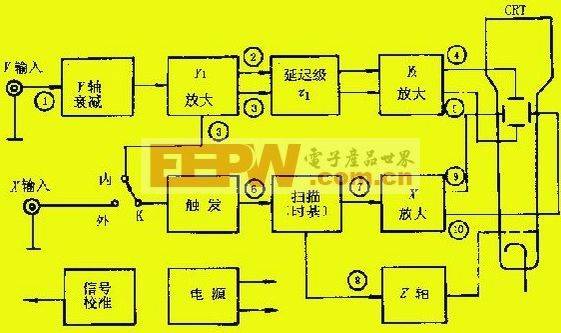
As shown in the figure above, the detected signal 1 is delivered to the "y" input end and is sent to the y1 amplifier by appropriate decay of the y-axis decayer, and then to the output signal 2 and 3 after y1. It is then delayed by a delay of one hour to the y2 amplifier. The magnification produces signals of 4 and 5 large enough to be added to the y-axis deflector plate of the oscilloscope. In order to display a full stabilization wave shape on the screen, the detected signal of the y axis 3 is introduced into the trigger circuit of the x-axis system, which produces a trigger pulse of a positive (or negative) level of an electrical level at which the signal is introduced, initiates a sawn-tooth scanning circuit and produces a scanning voltage 7。
In order to ensure that the x-axis scan begins before the y-axis signal reaches the fluorescent screen, the y-axis-seat-one should be slightly greater than the x-axis-one-seat-two-seat delay. Scan voltage 7 amplified by an x-axis amplifier, resulting in push-out 9 and 10, added to the x-axis steering panel of the oscilloscope. The z-axis system is used to magnify the scanned voltage positive and becomes a positive rectangular wave to the oscilloscope pole. This allows for a fixed light in the waveform shown at the scanning process, while the scanning back course is scrubbed。
These are the basic working principles of oscillators. Double-trace displays two different detected signals entered into the y axis using an electronic switch are displayed on the fluorescent screen. Two stable, clear signal waveforms are seen when conversion frequency is high, due to the temporary visualization of human eyes。